Choosing between metal injection molding and die casting can feel like comparing apples to oranges.
Both processes force material into a mold cavity to produce metal parts, but the similarities largely end there.
The right choice depends on your part size, material requirements, geometric complexity, and production volume.
This guide breaks down everything you need to know about metal injection molding vs die casting, from technical fundamentals to practical decision frameworks that will help you select the optimal manufacturing process for your next project.
When to Use Metal Injection Molding vs Die Casting?
Metal Injection Moulding (MIM) is typically best for small, highly complex parts weighing 0.1–100 grams made from high-performance alloys like stainless steel, tool steel, or titanium alloys.
These are applications where precision, material strength, and intricate components matter more than raw production speed.
Die casting, on the other hand, dominates when you need larger parts with simpler structural geometries in aluminum, zinc, or magnesium alloys.
This casting process excels when cost efficiency at very high production volumes is the primary driver.
The fundamental difference comes down to this: MIM uses fine metal powders mixed with binders that are sintered to near-full density, while die casting injects molten metal directly into hardened steel mold cavities.
What is Metal Injection Molding (MIM)?
Metal injection molding MIM represents a hybrid manufacturing process that combines the design freedom of plastic injection molding with the material performance of powder metallurgy.
The result is a metal manufacturing process capable of producing small, highly complex components in high-performance alloys that would be prohibitively expensive to machine conventionally.
Process Steps
MIM follows four distinct phases:
- Injection Molding: The feedstock is heated and injected into a hardened steel mold under pressure, forming a “green” part that holds its shape but remains fragile
- Debinding: Chemical or thermal processes remove most of the polymer binder, leaving a porous “brown” part composed primarily of metal powder
- Sintering: The brown part enters a high-temperature furnace where metal particles fuse together, shrinking the part by roughly 15–20% linearly
- Secondary operations: Optional heat treatment, machining, or surface finishing for critical dimensions
The sintering process achieves final density typically between 95–99% of theoretical full density.
Designers must account for this predictable shrinkage by scaling up cavity dimensions—usually by factors of 1.15–1.25 depending on the alloy and geometry.
Materials and Applications
MIM excels with materials that have high melting temperatures and would damage conventional die casting tooling:
- Stainless steels: 316L for corrosion resistance, 17-4PH for high strength after age hardening
- Low-alloy steels: For wear resistance and hardness
- Tool steels: 420, 440C for cutting edges and wear surfaces
- Titanium alloys: For medical implants and aerospace components
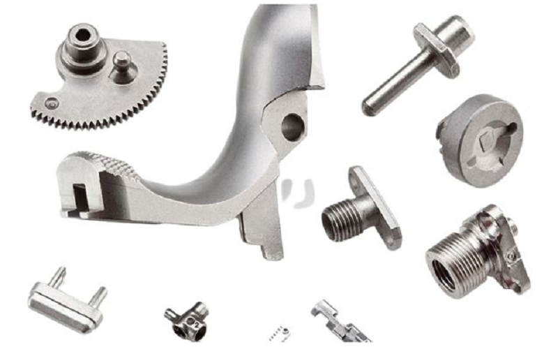
Typical applications include medical device components, orthodontic brackets, firearm components, watch parts, smartphone hardware, sensor housings, and small precision gears.
Part weights generally range from sub-gram components up to about 50–100 grams, with linear dimensions typically under 100 mm.
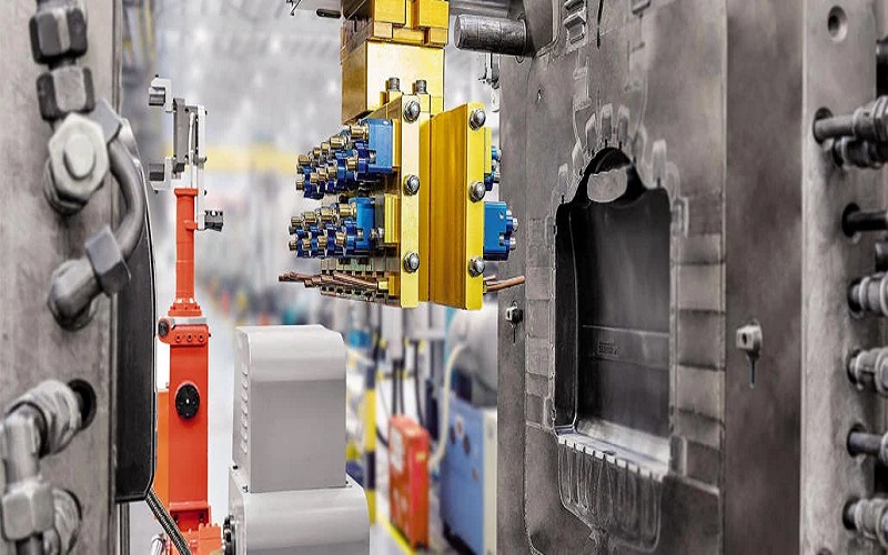
What is Die Casting?
Die casting is a high-pressure metal forming process where molten material is injected into hardened steel dies to produce components at rapid cycle times.
This manufacturing method has been a cornerstone of high volume production since the early 20th century, particularly for non ferrous metals like aluminum and zinc.
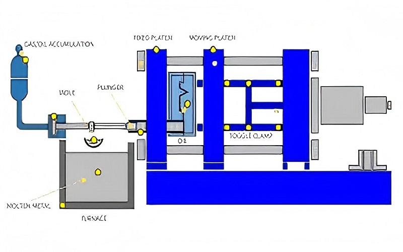
Basic Process Sequence
The die casting process follows a straightforward sequence:
- Melting: Alloy ingots are heated to liquid state in a furnace
- Injection: Molten metal injected into a two-part steel mold at high pressure
- Solidification: Rapid cooling occurs within the die, often in seconds
- Ejection: The die opens and the part is removed
- Trimming: Gates, runners, and flash are removed from the finished casting
Process Variants
Two main variants exist based on how the molten metal is delivered:
- Hot chamber: The injection mechanism is submerged in molten metal, enabling rapid cycle times. Used for low melting points materials like zinc alloys and some magnesium alloys.
- Cold chamber: Molten metal is ladled into a separate injection chamber for each shot. Required for aluminum and higher-melting non ferrous alloys that would attack submerged components.
Gravity die casting represents a lower-pressure variant where molten metal flows into the mold under gravity rather than high pressure injection.
Materials and Applications
Die casting produces parts from several alloy families:
| Alloy Family | Common Grades | Key Properties |
|---|---|---|
| Aluminum | A380, ADC12, A360 | Good strength-to-weight, thermal conductivity |
| Zinc | Zamak-3, Zamak-5 | Excellent detail reproduction, low melting point |
| Magnesium | AZ91D | Lightest structural alloy, good machinability |
| Copper-based | ZA alloys | Higher strength, wear resistance |
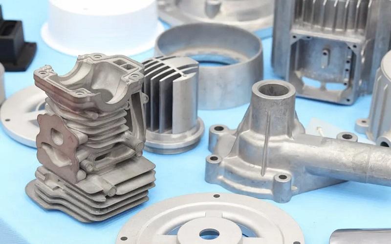
Die cast parts range from small connectors weighing around 30 grams to massive automotive housings exceeding 10 kg.
Some specialized machines can produce aluminum chassis components over 100 kg.
Common applications include automotive transmission and engine components, power tool bodies, LED lighting housings, appliance frames, and consumer electronics enclosures.
Key Technical Differences Between MIM and Die Casting
The fundamental difference between metal injection molding vs die casting lies in how the raw material enters the mold: MIM uses a paste of metal powder and binder that’s later sintered, while die casting injects fully molten metal that solidifies in place.
This distinction cascades through every aspect of design, tooling, and economics.
Shrinkage Behavior
MIM parts undergo dramatic, predictable shrinkage during the sintering process—typically 15–20% linear shrinkage for steel alloys.
This requires careful mold design with enlarged cavities and support structures to prevent distortion of thin walls and delicate features during densification.
Die cast parts experience minimal shrinkage after ejection—typically less than 1% linear contraction as the metal cools from solidification temperature to room temperature.
Dimensional accuracy is primarily controlled by die precision and thermal management rather than post-process changes.
Microstructure and Density
The two processes produce fundamentally different internal structures:
MIM microstructure:
- Fine, uniform grain structure from powder consolidation
- Residual porosity of 1–5% (spherical, isolated pores)
- Properties approach wrought materials when properly sintered
- Isotropic behavior in all directions
Die casting microstructure:
- Fine-grained “skin” from rapid surface cooling
- Coarser core with potential gas porosity
- Shrinkage cavities possible in thick sections
- Directional properties based on solidification pattern
Both processes rely on two-part steel tools with similar gating and venting concepts, but the specific priorities differ.
MIM tooling focuses on uniform filling and shrinkage management.
Die casting tooling emphasizes thermal fatigue resistance, metal flow optimization, and surviving repeated exposure to molten material at high pressure.
Advantages of Metal Injection Molding Compared to Die Casting
When evaluating metal injection molding vs die casting, MIM offers distinct advantages in several critical areas.
Understanding these strengths helps engineers identify applications where MIM delivers superior results.
Material Range
MIM’s ability to process metals with high melting temperatures opens material options impossible for die casting:
- Stainless steels: 316L delivers excellent corrosion resistance with tensile strength around 500–550 MPa; 17-4PH achieves 1,100–1,300 MPa after age hardening
- Tool steels: Hardened cutting edges and wear-resistant surfaces
- Titanium alloys: Biocompatible medical implants and aerospace components
- Superalloys: Nickel and cobalt-based materials for high temperatures
These ferrous metals and specialty alloys would either destroy die casting tooling or require impossible mold temperatures.
Surface Finish and Precision
MIM produces remarkably smooth surfaces directly from the sintering process:
- As-sintered finish: 0.8–1.6 µm Ra typical
- Very tight tolerances achievable on small features (±0.05 mm possible)
- Fine detail replication from small powder particle size
- Minimal post-processing required for many applications
Mechanical Properties
Metal injection molded parts exhibit mechanical strength approaching wrought materials:
When properly heat treated, 17-4PH MIM parts achieve tensile strengths of 1,100–1,300 MPa with yield strength around 1,000–1,200 MPa—comparable to bar stock.
The uniform, fine-grained microstructure provides isotropic properties and good fatigue performance, unlike die castings where porosity can create weak points under cyclic loading.
Advantages of Die Casting Compared to Metal Injection Molding
When part size, alloy choice, and production volume align with die casting’s strengths, this process can dramatically reduce unit cost and accelerate delivery.
Understanding where die casting produces superior results helps engineers avoid over-engineering with MIM when simpler solutions exist.
Production Speed
Die casting offers exceptional throughput once production stabilizes:
- Production cycle times often measured in seconds for aluminum and zinc parts
- Single machines producing thousands of parts per day
- Rapid cycle times enable high volume production economics
- Minimal batch processing—parts are essentially finished off the machine
MIM’s debinding and sintering steps add hours to days of processing time per batch, making die casting significantly faster for total lead time on production orders.
Size and Weight Range
Die casting supports much larger part envelopes than MIM:
| Dimension | MIM | Die Casting |
|---|---|---|
| Maximum weight | ~100 g practical | 10+ kg common |
| Maximum dimensions | ~100 mm typical | Several hundred mm |
| Wall thickness range | 0.3–6 mm | 0.8 mm – thick sections |
For structural housings, brackets, and enclosures in automotive and industrial equipment, die casting handles sizes that would be impractical or impossibly expensive in MIM.
Raw Material Simplicity
Die casting feedstock requires minimal preparation:
- Standard alloy ingots from suppliers
- Recycled runners and gates remelted directly
- Lower cost per kilogram than engineered MIM powders
- Established supply chains for common alloys
MIM feedstock involves expensive fine metal powders, engineered binder systems, and careful mixing—all adding to material costs.
Key Differences :Comparing Tooling Cost, Speed, and Production Volume
Both MIM and die casting require significant tooling investment, making the economic choice heavily dependent on lifetime volume and part complexity.
Understanding the cost drivers helps engineers identify the crossover points where one process becomes more economical.
Tooling Investment
Both processes require hardened steel mold or die construction:
| Factor | MIM | Die Casting |
|---|---|---|
| Tool material | Hardened tool steel | Hardened H-13 or equivalent |
| Complexity drivers | Fine features, multiple cavities | Thermal management, slides |
| Typical lead time | 8–16 weeks | 10–20 weeks |
| Tool maintenance | Lower thermal stress | Higher wear from molten metal |
Die casting tools generally cost more due to the extreme operating conditions, but both processes run into thousands or tens of thousands of dollars for production-quality multi-cavity tools.
Per-Part Cost Drivers
MIM cost components:
- Fine metal powder (significantly more expensive than bulk alloys)
- Binder materials and mixing
- Debinding energy and consumables
- Sintering furnace time and atmosphere
- Inspection (often including CT scanning for porosity)
- Possible heat treatment
Die casting cost components:
- Alloy ingot cost
- Melting energy
- Machine operating time
- Trimming and gate removal
- Machining critical surfaces
- Surface finishing and coating
Volume Break-Even Points
The economic crossover between processes depends on part characteristics:
- Below 10,000 units: MIM can be competitive for small, complex parts where machining alternatives are expensive
- 10,000–100,000 units: Sweet spot for MIM on complex metal components; die casting competitive for simpler shapes
- Above 100,000 units: Die casting generally offers lower cost per piece, especially for larger parts in aluminum or zinc
For producing small, intricate parts in steel alloys, MIM often wins even at moderate volumes because machining would be prohibitively expensive.
For large production volumes of medium production runs in non ferrous alloys, choose die casting, die casting’s speed advantages dominate.
Design, Size, and Wall Thickness Considerations
Geometry and scale often decide between MIM and die casting before cost analysis enters the picture.
Each process imposes distinct constraints on what shapes are manufacturable and economical.
MIM Design Parameters
MIM excels at thin walls and intricate features but requires careful attention to uniformity:
Wall thickness:
- Minimum: ~0.3–0.5 mm achievable in stainless steels
- Optimal: 1–3 mm for reliable processing
- Maximum: ~6–10 mm limited by debinding and sintering challenges
Design best practices:
- Maintain uniform wall thickness to prevent distortion during sintering
- Use smooth transitions between thick and thin sections
- Generous fillets reduce stress concentration and improve flow
- Avoid isolated heavy masses that complicate debinding
- Support delicate features to prevent slumping in furnace
Ideal MIM features:
- Cross-drilled holes
- Internal threads
- Micro gear teeth
- Fine surface textures
- Complex internal channels
Die Casting Design Parameters
Die casting handles broader absolute size ranges but struggles with certain geometries:
Wall thickness by alloy:
- Aluminum: ~1–2 mm minimum typical
- Zinc: ~0.5–1 mm (higher fluidity enables thinner walls)
- Magnesium: ~1.5 mm typical minimum
Design requirements:
- Draft angles required for ejection (typically 1–3°)
- Ribs and bosses preferred over solid masses for stiffness
- Venting critical for gas escape
- Cooling channel design affects cycle time and quality
- Avoid deep, thin isolated features
Ideal die casting features:
- Large mounting pads
- External ribs for stiffness
- Integral cooling fins
- Boss structures for fasteners
- Smooth external surfaces
Post-Processing, Tolerances, and Surface Finish
Neither process always delivers parts ready for assembly straight from the tool. Understanding typical secondary operations helps engineers plan realistic production flows and cost estimates.
MIM Post-Processing
MIM is designed for near-net shape production, with many parts requiring only minor secondary operations:
Common operations:
- Sizing or coining for critical dimensions
- Local machining on mating surfaces
- Heat treatment (age hardening for 17-4PH, quench and temper for tool steels)
- Surface finishing (polishing, passivation for stainless)
Typical tolerances:
- General: ±0.3–0.5% of nominal dimension
- Critical features: ±0.05–0.1 mm achievable with care
- Feature-to-feature: Excellent consistency within a part
Surface finish:
- As-sintered: 0.8–3.2 µm Ra typical
- Polished: Can achieve mirror finish
- Minimal tool marks compared to machining
Die Casting Post-Processing
Die cast parts frequently require more secondary work due to process characteristics:
Common operations:
- Trimming gates, runners, and flash (always required)
- Drilling and tapping holes
- Machining critical mating surfaces
- Surface finishing (shot blasting, polishing)
- Coating (anodizing, painting, plating)
Typical tolerances:
- Linear: ±0.1 mm on first 25 mm, scaling proportionally
- Flatness: May require machining for precision surfaces
- Hole locations: ±0.2 mm typical without machining
Surface finish:
- As-cast: 1.6–6.3 µm Ra typical
- Flash lines and die marks often visible
- Secondary finishing common for cosmetic parts
Summary
The choice between metal injection molding vs die casting ultimately comes down to matching your part’s requirements with each process’s fundamental strengths.
MIM transforms fine metal powders into small, intricate components with tight tolerances and exceptional mechanical properties.
Die casting rapidly produces larger structural parts in non ferrous alloys at the lowest possible per-piece cost for high volume production.
The best decisions come from engineers who understand both options deeply enough to recognize when each process delivers superior results.
Whether your next project calls for MIM’s precision in steel or die casting’s efficiency in aluminum, matching the process to the part ensures you achieve the dimensional accuracy, material strength, and cost targets your application demands.