
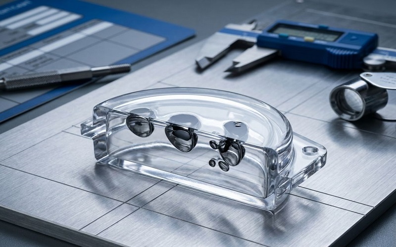
Voids are a common and significant defect in the injection molding process that affect product quality. The formation of voids not only weakens the structural strength of plastic parts but can also cause surface depressions, cracks, and other issues, impacting the final product’s appearance and performance.
This article will explore in depth the main causes of voids in injection molding, the different types of voids, and how to effectively prevent their occurrence by optimizing process parameters and mold design.
This will help injection molding manufacturers improve the overall quality and production efficiency of molded parts.
What Are Injection Molding Voids ?
Injection molding voids are internal cavities or empty spaces that form within injection molded parts during the manufacturing process.
These voids typically occur when the molten plastic material does not completely fill the mold cavity or when trapped air, gas, or shrinkage effects create pockets inside the part.
Voids can vary in size and shape and often appear in thick sections or areas where two flow fronts meet but fail to bond properly. In consumer-facing components, they can also affect aesthetic appeal by causing visible surface defects.
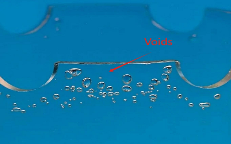
Main Types Of Voids In Injection Molding
To reduce injection molding voids, first determine whether the defect is a vacuum void caused by shrinkage or a gas void caused by air, moisture, or material degradation.
Inspect the defect’s location and appearance, and review process records, material-drying conditions, and mold venting.
Internal defects may not be visible on the surface. If needed, confirm the location and extent of voids by sectioning the part or using nondestructive testing methods such as ultrasonic testing or X-ray imaging.
Vacuum Voids
Vacuum voids occur when the plastic cools and shrinks inside the mold cavity, creating empty spaces where the material has contracted.
This type of void is typically caused by insufficient packing pressure or holding pressure during the cooling phase, which fails to compensate for material shrinkage. Vacuum voids often appear in thick sections or ribs where the material cools unevenly.
Gas Pockets and Bubbles
Gas voids form inside a mold when air or other gases become trapped in the plastic. Common sources include air entrapment during injection, moisture vaporization in hygroscopic resins, and gases released by material degradation.
These pockets can appear as bubbles within the part and may also cause surface defects such as burn marks or splay. Poor venting and unsuitable mold design can make gas voids more likely to occur.
Weld Line Voids
Weld line voids develop where two or more flow fronts of molten plastic meet but fail to fuse properly. This results in weak spots with visible lines or seams on the surface of the part. Poor gate placement, low melt temperature, or excessive injection speed can contribute to weld line voids.
Sink Marks
Sink marks are surface depressions caused by localized shrinkage in thicker sections of the part. They are typically caused by insufficient packing pressure or inadequate cooling time, which prevents the plastic from fully compensating for material shrinkage.
Sink marks often indicate voids beneath the surface and can affect both the aesthetics and structural integrity of the part.
Air Traps
Air traps are pockets of air that become enclosed within the part during the injection process. These trapped air pockets can cause internal voids and surface blemishes. They are usually the result of poor mold venting, improper gate design, or high injection speed that traps air before it can escape.
Each type of void formation is typically caused by a combination of processing conditions, material properties, and mold design factors.
Addressing these issues requires a comprehensive approach that includes optimizing injection pressure, injection speed, mold temperature, and packing pressure, as well as improving mold venting and part design to prevent air entrapment and differential shrinkage.
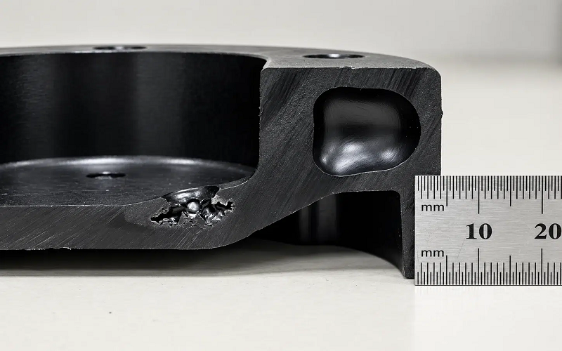
Root Causes Of Voids In Injection Molded Parts
Voids in injection-molded parts are mainly caused by a combination of material properties, processing parameters, and mold design. Understanding these root causes is essential for preventing void formation and ensuring part quality.
Material Properties
Resin properties and moisture content can affect void formation.
Moisture in Hygroscopic Resins
In hygroscopic plastics, excessive moisture can generate steam during molding, resulting in bubbles inside the part. Using properly dried material and selecting a suitable resin can minimize gas formation and improve part integrity.
Thermal Degradation And Restricted Flow Path
Material flow properties and thermal stability also affect void formation. Poor material flow can cause incomplete filling and create voids, while thermal degradation may release gases and increase the risk of gas voids.
Mold-Related Causes
Mold design plays a critical role in preventing voids.
Improper Gate Location
Improper gate placement can create uneven material flow, which may lead to air entrapment and void formation.
Uneven Cooling Channels
Thick sections without adequate cooling channels are more likely to develop internal voids because they cool slowly. Properly designed cooling channels help maintain a uniform mold temperature and prevent differential shrinkage caused by uneven cooling, thereby reducing the risk of voids.
Inadequate Venting
If the mold’s venting system is inadequate, air cannot escape and may become trapped inside the part, forming voids. Properly positioned vents and channels allow air to escape in time and reduce the risk of trapped gas in the mold.
Processing Parameters
Injection molding parameters such as injection pressure, injection speed, holding time, and cooling time directly affect void formation.
Low Holding Pressure
Insufficient injection pressure or a holding time that is too short cannot adequately compensate for material shrinkage during cooling, leading to vacuum voids. Excessive injection speed may entrap gas and create gas voids.
Improper Melt Or Mold Temperature
Incorrect melt or mold temperatures can affect material flow and lead to voids. If the melt temperature is too low, the plastic’s viscosity may be too high to fill thin sections, or the material may solidify before reaching the end of the cavity, resulting in a short shot.
Mold temperature affects the cooling rate. A temperature that is too low can cause the outer layer of the part to solidify prematurely, restricting plastic flow into thicker sections. A temperature that is too high or unevenly distributed may extend cooling time, cause differential shrinkage, and increase the risk of voids.
Insufficient Cooling Time
Controlling cooling time and cooling rate is also essential. Uneven cooling rates within the mold can cause differential shrinkage and contribute to void formation.
Thicker sections and areas with complex geometries often cool more slowly than thinner sections. As a result, the outer surface may solidify while the inner core remains molten.
By adjusting material selection, mold design, and processing parameters together, manufacturers can control material flow and cooling, prevent void formation, and improve the quality and performance of injection-molded parts.
| Cause Category | Vacuum (Shrinkage) Voids | Gas Voids / Bubbles |
|---|---|---|
| Process | Low packing pressure/time, early gate freeze, high melt temp | High injection speed, low back pressure, high melt temp |
| Mold | Undersized/poorly located gates, uneven cooling | Poor venting |
| Material | High-shrinkage grades | Moisture, degradation, contaminated regrind |
| Design | Thick walls, abrupt thickness changes | Complex geometry that traps air |
How To Prevent and Solve Injection Molding Voids?
To eliminate voids effectively, adjust factors in this order—first the process, then the material, and finally the mold and part design—to minimize production downtime:
Optimize Process Parameters
- Increase Injection Pressure and Holding Time: For shrinkage voids, gradually increase injection and holding pressure, and confirm that the cavity is fully filled before switching to the holding stage. Extending holding time can help compensate for shrinkage, but it has limited effect after the gate freezes. Adjust it in conjunction with gate size and cycle time.
- Optimize Melt and Mold Temperatures: Keep the melt temperature within the range recommended for the material. Temperatures that are too low can hinder filling, while excessive heat may degrade the resin. Check that cooling circuits are clear and that coolant flow and temperature are stable, paying particular attention to thick sections that cool more slowly.
Fix Material Preparation
- Dry the Resin Thoroughly: Dry hygroscopic plastics according to the resin supplier’s recommendations, and verify that the drying temperature, duration, and dew point are appropriate. Moisture, contamination, or thermal degradation can generate gas. If you notice silver streaks, burn marks, or an unusual odor, check barrel residence time, melt temperature, and material condition.
- Choose a Low-Shrinkage or High-Flow (Low-Viscosity) Resin: If the part’s strength, heat resistance, and other performance requirements allow, consider a material with a lower shrinkage rate to reduce the amount of shrinkage compensation needed. A high-flow resin can also fill complex part geometry and thin sections more easily.
Modify Mold & Part Design
- Improve Mold Venting: If voids are caused by trapped gas, inspect the parting line, vent grooves, ejector-pin clearances, and end-of-fill areas to ensure air can escape. Clean blocked vents and adjust their positions as needed. Vents must not be too deep, or they may cause flash.
- Change Gate Location and Size: Follow the principle of filling from thick sections toward thin sections, and place the gate directly at the thickest area of the part. Increasing the gate’s cross-sectional area can prevent premature gate freeze and help holding pressure reach deeper into the mold cavity.
- Maintain Uniform Wall Thickness: Uniform wall thickness promotes consistent cooling, while avoiding excessive thickness helps prevent sink marks and internal voids.
When modifying cooling channels, gates, or vents in a plastic injection mold, use mold-flow analysis and trial results to guide the solution.
During troubleshooting, change only a few parameters at a time and record the defect’s location and size, pressure curves, material batch, and cycle time.
If increasing holding pressure reduces voids, shrinkage compensation is likely insufficient. If improved drying or venting reduces bubbles, moisture or trapped air is a more likely cause.
Systematically validate the process, material, mold, and part design to find reliable mold solutions rather than relying on continuous pressure increases to mask the problem.
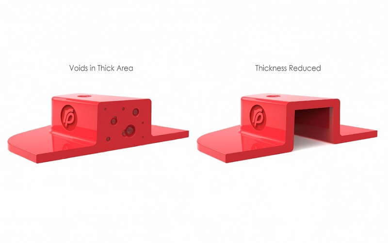
Conclusion
Injection molding voids can weaken parts, damage their appearance, and lead to premature failure. They usually result from material shrinkage, trapped gas or moisture, inadequate packing, uneven cooling, or mold and part design issues.
Preventing them requires identifying the void type and addressing its root cause through suitable drying, optimized injection and holding pressure, effective venting, uniform cooling, and well-designed gates and wall thicknesses.
Systematic testing and process records help manufacturers verify improvements and produce more consistent, reliable parts.