In the contemporary landscape of precision manufacturing, the ability to consolidate multiple functional requirements into a single, high-performance component is a competitive necessity.
Insert molding stands at the forefront of this evolution, offering a sophisticated manufacturing process that transcends the limitations of traditional mechanical assembly.
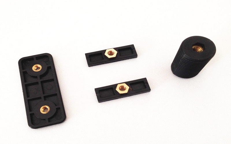
By integrating pre-formed components—typically metal—directly into a molded part, engineers can achieve levels of structural integrity and functional density that are otherwise unattainable.
This guide serves as a technical roadmap for navigating the complexities of the insert molding process, ensuring that your product development process yields robust, cost-effective, and high-quality results.
Understanding Insert Molding
To master insert molding design, one must first grasp the physical interplay between the pre-made component and the injected material.
Unlike standard injection molding, where the mold cavity is entirely filled by a single plastic material, insert injection molding requires the precise suspension of an insert within the tool before the cycle begins.
This synergy allows designers to combine materials, leveraging the mechanical properties of metals—such as electrical conductivity, corrosion resistance, and high tensile strength—with the geometric flexibility and lightweight nature of plastic components.
Insert molding is a manufacturing process that integrates pre-formed metal or plastic components into a complete part during the injection molding cycle.
This foundational concept allows for the creation of multi-material parts that exhibit superior performance in demanding environments.
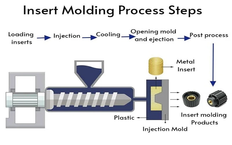
The molding process begins with insert placement, which can be handled via manual loading for low-volume prototypes or automated via robotics for high-volume production.
Once secured, molten plastic is forced into the mold cavity under high injection pressure.
As the injected material flows, it must fully encapsulate the insert without displacing it, a challenge that requires meticulous mold design and precision tooling.
The Anatomy of the Insert Molding Process
Navigating the transition from simple plastic molding to complex insert molded components requires a deep dive into the operational sequence of the injection molding machine.
The process is not merely about “surrounding an object with plastic”; it is about managing fluid dynamics, thermal transfer, and mechanical interlocking in a single, rapid cycle.
The insert molding process involves placing subcomponents into the mold cavity before molten plastic is injected around them.
This sequence is critical because the insert placement defines the final part geometry.
During the cycle, the injection molding machine forces molten thermoplastic into the mold, ensuring that the resin flows smoothly and evenly around the insert.
If the flow is imbalanced, the resulting injection pressure can cause “insert shift,” leading to dimensional inaccuracies or even tool damage.
Once the part solidifies, ejector pins push it out of the mold, ensuring the insert remains securely bonded within the encapsulating plastic.
Material Selection and Compatibility
The success of insert molded parts is heavily dictated by the chemical and thermal relationship between the overmolded material and the insert itself.
Material compatibility is crucial for successful insert molding, as mismatched materials can lead to structural failures.
When selecting a plastic material, engineers often turn to high-performance resins.
The common plastic resins used in insert molding include ABS, nylon, polycarbonate, and thermoplastic elastomers.
For more specialized applications, thermoplastic polyurethane or acrylonitrile butadiene styrene (ABS) are utilized to meet specific tactile or impact requirements.
Insert molding combines metal and plastic in one step.
On the other hand, the inserts are not limited to ferrous metals. Inserts can be made from materials such as brass, steel, stainless steel, aluminum, or plastics that withstand processing conditions.
While metal inserts are widely used in insert molding for mechanical reinforcement or electrical conductivity, some designs employ plastic insert injection molding, which uses high-performance engineered plastics when the base molding material lacks specific properties.
| Insert Material | Common Plastic Base | Typical Application |
| Stainless Steel | Polycarbonate | Medical devices (Surgical tools) |
| Brass | ABS | Threaded metal inserts for electronic components |
| Aluminum | Thermoplastic elastomers | Lightweight structural support in automotive |
| Ceramic | PEEK / PPS | High-temp sensors and circuit boards |
| Rigid Plastic | Thermoplastic polyurethane | Multi material parts with soft-touch grips |
Advanced Material Considerations for Engineers
In the realm of advanced manufacturing processes, simply choosing a resin is insufficient; one must evaluate how material selection for insert molding influences plastic flow, which directly impacts encapsulation quality.
This is particularly true when dealing with multiple materials that have vastly different cooling rates.
For instance, insert molding can accommodate components made from specialized materials such as ceramic inserts, which offer exceptional heat resistance and electrical insulation.
However, common plastic inserts include glass-filled composites, PEEK, and PPS, which provide high dimensional stability.
A mechanical engineer must also account for chemical compatibility; if the molten plastic does not “wet” the insert surface properly, or if the chemicals in the resin react with the metal’s surface treatments, the structural integrity of the molded part will be compromised.
Insert molding is compatible with a wide range of materials, including metals and engineered plastics, but the harmony between their thermal expansion coefficients is the invisible thread that holds the assembly together.
Critical Design Guidelines: Ensuring Structural Integrity
Designing for insert molding offers significant advantages, but it also introduces unique failure modes.
Key considerations for insert molding include secure mechanical retention, consistent plastic wall thickness, managing thermal expansion, and proper mold sealing.
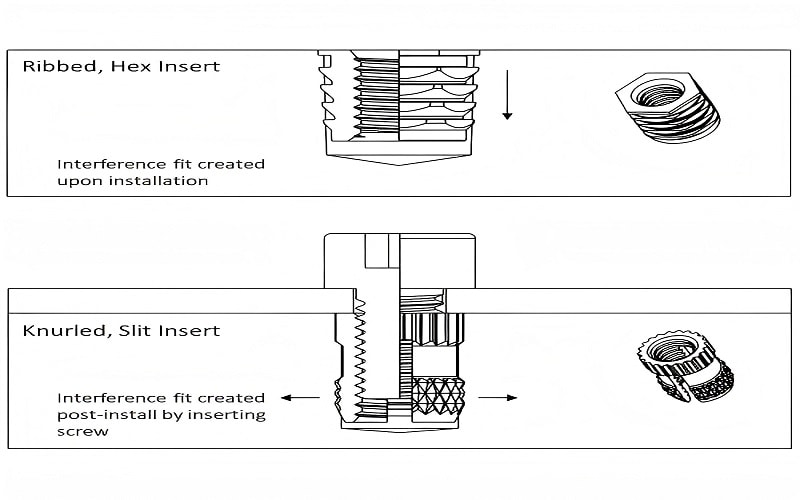
Because metal inserts do not establish chemical bonds with over-molded plastic components, mechanical bonding must be designed into the components.
Without mechanical retention features like knurls, grooves, or undercuts, the insert will likely fail under torque or pull-out forces.
One of the most frequent issues is thermal expansion mismatch, where the metal and plastic expand and contract at different rates during the molding process.
Thermal expansion mismatch between metal and plastic can create internal stress that weakens durability.
To mitigate this, maintaining uniform wall thickness around the insert is non-negotiable. Uniform wall design around inserts helps protect high-load zones and prevents stress concentration.To ensure a lifetime of reliability, the part geometry must facilitate a permanent lock.
Using knurls, grooves, and undercuts on inserts improves mechanical retention and prevents pull-out failures.
These features allow the surrounding plastic to “grip” the insert physically.
Furthermore, the plastic boss surrounding an insert should have an outer diameter of at least 1.5 times the insert’s diameter to avoid cracking.
This rule of thumb provides enough plastic material to withstand the hoop stresses generated during cooling.
Proper draft angles ranging from 1 to 2 degrees are essential for easy ejection of parts from the mold.
Without these angles, the molded plastic may grip the mold cavity too tightly, leading to deformation or sink marks upon ejection.
Additionally, insert shape directly impacts pull-out resistance, and strong mechanical interlocking prevents bond failure under cyclic stress.
Optimizing the Manufacturing Process
Efficiency in volume production is achieved through rigorous process control.
Proper Process Control
Proper process control, including melt temperature and injection pressure, directly impacts bond strength in insert molding.
High injection pressure is necessary to eliminate voids and ensure the injected material reaches every crevice of the mechanical retention features, but it must be balanced to prevent insert placement issues.
Placement methods for inserts can vary between manual loading for prototypes and automated robotic placement for high-volume production.
Regardless of the method, inserts must be manufactured with tight tolerances, typically ±0.002 inches (±0.05 mm), to avoid issues with plastic flash or difficulty in mold closure.
If an insert is too large, the mold won’t seal; if it is too small, molten plastic will leak into the threaded inserts, requiring costly post molding assembly cleaning.
Simulation and Validation Techniques
Modern mold design relies heavily on digital validation to avoid the “trial and error” phase of product development.
Manufacturing processes for inserts should utilize simulation tools like Moldflow analysis to predict resin behavior around the insert.
By simulating the injection molding process, engineers can identify where weld lines will form.
Conducting mold flow analysis is essential to verify complete encapsulation and eliminate air traps around inserts.
It also helps in gate placement; specifically, inserts should be strategically placed away from the gate locations to avoid displacement during injection.
If the gate is too close, the high-velocity stream of molten plastic can knock the insert out of alignment.
Furthermore, preheating inserts before molding helps minimize post-mold shrinkage and improves weld-line strength, as it reduces the thermal shock to the molten plastic upon contact.
Industry Applications and Strategic Advantages
Why do leading firms choose insert molding over other methods? The answer lies in the total cost of ownership.
Insert molding eliminates the need for separate assembly steps, saving time and labor costs.
By eliminating secondary fastening such as screws or adhesives, the final product is often lighter and more compact.
Insert molding integrates dissimilar materials into durable integrated components, reducing assembly time and enabling compact designs across major manufacturing sectors.
Applications of Insert Molding in Various Industries
In the medical field, syringe needle hubs integrate plastic bodies with stainless steel shafts for sterile, single-use components in medical devices.
In the automotive sector, automotive manufacturers use insert molding for high-performance plastic parts that endure heat, vibration, and stress.
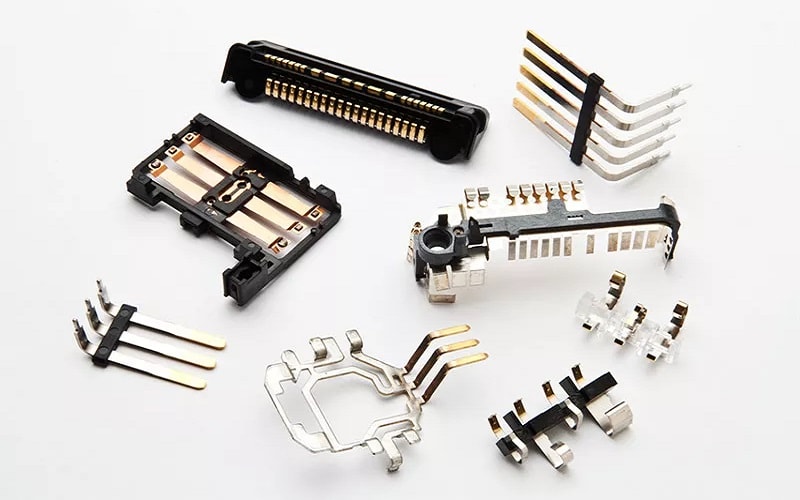
Even in consumer electronics, insert injection molding enables compact, reliable electronic components by embedding metal inserts into plastic bodies for electrical contact and strain relief.
Advantages of Insert Molding Applications
The molding capabilities of this manufacturing process is evident in how it handles multiple materials and functions.
Insert molding is widely used in industries ranging from consumer products to automotive and electronic components.
It allows for efficient heat transfer when using metal parts as heat sinks within plastic housings.
In harsh industrial settings, insert-molded components withstand high loads and wear, ensuring stable mechanical movement.
Whether it is threaded fasteners in a power tool or circuit boards encapsulated for moisture protection, insert molding offers a level of reliability that post molding assembly rarely matches.
Ultimately, insert molding allows for the creation of strong, functional, and lightweight parts in a streamlined and cost-effective manner.
Troubleshooting Common Defects in Insert Molding
Despite its benefits, the molding process can present hurdles if key design considerations are ignored.
Potential Issues in Insert Molding
Delayed cracking in the plastic surrounding metal inserts is a common defect associated with insert molding, often caused by residual stresses from a thermal expansion mismatch.
Similarly, sink marks can appear if the wall thickness is not uniform or if the cooling time is insufficient.
Inadequate cooling time can cause warpage or microcracks near insert interfaces, particularly with materials like nylon or glass-filled composites.
Furthermore, excessive injection speed can shift or tilt inserts during the molding process, compromising alignment.
To prevent these issues, engineers must prioritize mechanical retention geometry, as weak retention geometry can lead to structural failure in insert molded parts.
- Inserts can loosen, crack the housing, or pull out entirely if not designed properly.
- Improper insert placement can lead to misalignment and bonding issues.
- Poor process control can compromise bond strength.
- Sharp corners contribute to stress concentrations; using rounded geometry and fillets improves flow.
Refine Insert Molding Design
To conclude, proper design for the insert molding process ensures the inserts bond securely with the encapsulating plastic, creating durable, functional parts in one cycle.
By adhering to the principles of uniform wall thickness, utilizing mold flow analysis, and selecting compatible plastic components and metal inserts, you can achieve a superior product.
Insert molding designs require securing metal or rigid components inside a mold before injecting plastic, and every detail—from the knurls to the injection pressure—must be calculated.
Conclusion
Ultimately, the insert molding process is about achieving high-performance synergy between multiple materials.
By embedding metal parts directly into the molded plastic, engineers create robust threaded metal inserts capable of withstanding repeated assembly without failure.
While the use of specialized equipment and precision tooling requires an initial investment, the return is seen in superior structural integrity and reduced assembly steps.
For projects requiring high production volumes, choosing insert molding over two shot molding often provides a more cost effective and durable result.
Proper design for the insert molding process ensures the inserts bond securely with the encapsulating plastic, delivering a reliable, integrated component that meets the most demanding industrial standards.