Mould design for injection moulding is crucial for producing precise, high-quality plastic parts. This process ensures material flow, uniform cooling, and part accuracy.
This guide covers essential elements like core and cavity, draft angles, and wall thickness. Understanding these will help you design effective moulds for your injection moulding needs.
Importance of Mould Design in Injection Moulding
Mould design is the linchpin of the injection molding process, directly influencing the quality and appearance of the finished product. The advantages of plastic injection molding are numerous, including high tolerance precision and the ability to produce multiple parts per cycle, which significantly enhances production efficiency. This process offers highly repeatable and essentially identical parts, making it a preferred choice for high-volume production with injection molding machines.
Cost-effectiveness is another notable benefit of injection molding. Compared to other manufacturing methods, injection molding leverages advanced material properties, such as liquid silicone rubber, to reduce overall low cost.
However, achieving a balance of optimum performance and cost-effectiveness hinges on designing the part correctly for injection molding. Involving an injection molder early in the design process is crucial for addressing potential design challenges, ensuring that the molten plastic, guided by features like hot tip gates, enters, fills, and cools within the cavity as intended.
Engaging in early communication with an injection molder can help identify risks and optimize the mold design, including the precise alignment of the halves of the mold. Understanding the behavior of injection molding materials and the intricacies of the injection molding process allows designers to preemptively address potential issues, resulting in smoother production cycles and higher-quality parts.
Mould design is foundational to the success of any injection molding project, influencing everything from the efficiency of the injection molding press to the final appearance of the parts. Each component of the mould, including hot tip gates, liquid silicone rubber compatibility, and the halves of the mold, plays a critical role in the overall molding process.
Key Elements of Mould Design
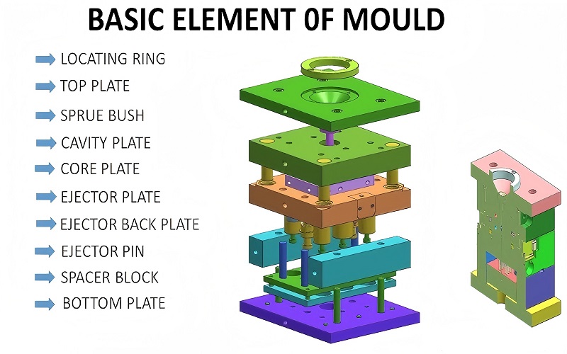
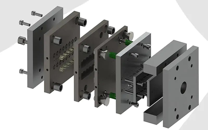
Key elements of mold building design are crucial for anyone involved in injection molding. The core and mold cavity are central to shaping the final product during the injection process, ensuring the part’s geometry avoids issues like sharp corners that can complicate molding or weaken the final product. The mold base, a foundational framework composed of various plates and components, supports the entire mold structure, ensuring stability and precision during molding.
The materials used for the core and cavity, typically steel or aluminum, are chosen for their durability and ability to withstand the rigors of the injection molding cycle. These materials must be carefully selected to match the specific requirements of the injection molding project, including the type of plastic resin being used and the desired properties of the final product, as well as compatibility with the runner system that delivers molten plastic to the cavity.
Guiding systems, consisting of guide pillars and bushings, ensure accurate alignment and movement of the mold components. These systems are critical for maintaining the precision and consistency of the injection molded parts. In a typical injection mold setup, the mold has two sides commonly referred to as A and B sides, which align to form the cavity when the mold closes, with the runner system facilitating efficient material flow to avoid defects caused by sharp corners.
Each of these elements plays a crucial role in the overall injection molding design. Understanding the functions and interactions of these elements allows designers to create molds that produce high-quality parts efficiently and consistently. Next, we’ll explore draft angles in mould design and their role in part ejection.
Draft Angles in Mould Design
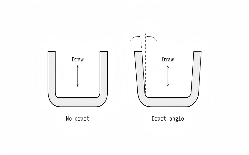
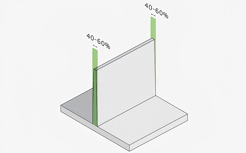
Draft angles are a fundamental aspect of injection mold design, essential for the easy ejection of parts from the mold. Without appropriate draft angles, parts can stick to the mold due to a vacuum effect, leading to defects such as drag marks and difficult ejection. The recommended minimum draft angle for vertical walls is 2 degrees, which helps ensure smooth ejection and prevents damage to the molded part, particularly when using precise manufacturing techniques like electrical discharge machining to create intricate mold features.
When parts have vertical walls and lack a draft angle, the likelihood of drag marks developing rises considerably. This is a key consideration in the design process. Features taller than 50 mm require an increased draft angle, adding one degree for every 25 mm to facilitate ejection. Additionally, more aggressive textures necessitate larger draft angles to ensure smooth ejection during the process, especially when molten plastic is delivered through tunnel gates in the mold.
Different resins have varying draft angle requirements based on their unique properties. Consulting with mold designers is crucial for determining the appropriate draft angle for specific materials and parts. For instance, snap features need at least a 5-degree draft angle if there are no core-pulls involved, and ribs typically require a draft angle of 12 degrees per side, with electrical discharge machining often used to achieve the precision needed for such features.
Draft angles are essential in preventing defects and ensuring smooth ejection of parts. Considering the properties of the plastic material and the part design, Lill helps designers determine optimal draft angles for high-quality, defect-free products, with tunnel gates aiding in efficient material flow. Next, we’ll delve into wall thickness considerations, another critical aspect of injection mold design.
Wall Thickness Considerations
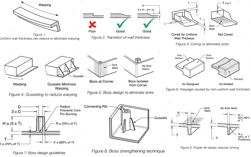
Maintaining uniform wall thickness is a cornerstone of effective injection molding design. Inconsistent wall thickness can lead to a host of problems, including uneven resin flow, air trapping, and ultimately defects such as warping and cracking. To ensure consistent cooling and minimize these defects, it is vital to maintain uniform wall thickness throughout the part.
For effective part design, consider the following recommendations regarding wall thicknesses:
- Keep wall thickness within a 10% variation.
- If uniform thickness cannot be achieved, use gradual smooth transitions to avoid abrupt changes that can cause stress concentrations and defects.
- Be aware that thin walls and thick walls each have their own set of challenges.
- Maintain a nominal wall thickness to help mitigate these issues.
Proper wall thickness is crucial for achieving high-quality injection molded parts. By adhering to these guidelines, designers can ensure that the parts cool uniformly, reducing the risk of defects and improving the overall quality of the final product, including considerations for thick sections and thick wall sections.
Next, we’ll explore how to manage undercuts in mould design.
Managing Undercuts
Undercuts present a unique challenge in injection molding, as they are part features that cannot be produced with a simple two-part mold due to material obstructions during mold opening or ejection, particularly when manufacturing plastic parts with intricate designs. Various techniques, such as slides or sliders, bumpoffs, and shifting the parting line, are employed to manage undercuts. Slides or sliders move with the mold’s opening to aid in demolding parts with undercuts.
Bumpoffs utilize a machined insert to create undercuts, allowing for easy part release, especially for parts reinforced with materials like glass fibers for added strength. Side-actions can help form complex features, like holes in tubular parts, by incorporating additional moving components into the mold design. Shifting the parting line of the mold can also effectively address undercuts, simplifying the ejection process.
While managing undercuts adds complexity and maintenance requirements to the injection molding process, it is often necessary for manufacturing plastic parts with detailed and functional features, such as those enhanced by glass fibers. For example, the teeth of threaded inserts, commonly found in items like bottle caps, are a type of undercut that requires careful mold design to produce. Lifters are smaller mechanisms used to aid in the ejection of parts with undercuts from the mold.
Managing undercuts effectively is crucial for producing high-quality parts with complex features. These techniques allow designers to create molds that facilitate easy part ejection and maintain product integrity. Next, we’ll discuss gate design and placement.
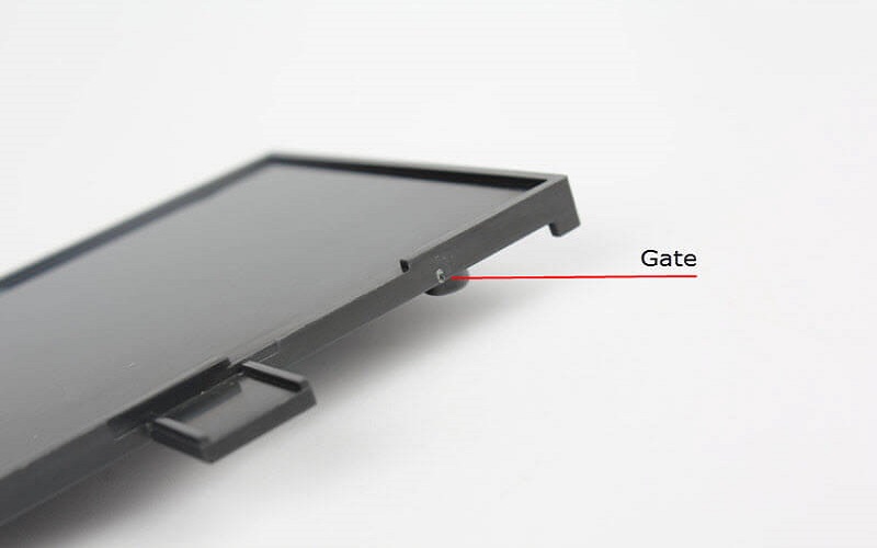
Gate Design and Placement
Gate design and placement are pivotal in achieving optimal material flow and minimizing defects in injection molded parts. The most common injection molding gates include:
- Edge gate: Best suited for flat parts and provides effective filling.
- Sub gates: Can be inconspicuously placed to maintain the aesthetic appearance of the product.
- Fan gates: Offer even distribution of melt in the cavity but can complicate gate removal.
Automatically trimmed gates incorporate features to break or shear gates when the tool opens, facilitating removal and enhancing production efficiency. Proper gate placement is crucial for minimizing melt fracture and ensuring consistent material flow, which helps to minimize shrinkage and enhance the overall quality of the molded part. The gate should be positioned in thicker parts of the wall to facilitate complete mold filling, while manually trimmed gates can also be considered for specific applications.
Utilizing compound gates can prevent deformation in large or flat plastic parts, enhancing overall product quality. Careful selection of gate locations is essential to minimize visible weld lines and maintain the structural integrity of the molded part. The design of the gate must accommodate the specific plastic flow characteristics of the selected plastic material to ensure efficiency, particularly for each plastic part involved.
Gate design and placement are crucial for achieving high-quality parts. Careful consideration of the gate type and its placement optimizes material flow and minimizes defects. Next, we’ll explore cooling system design in injection molds.
Cooling System Design
Cooling system design is a crucial aspect of injection molding, as the cooling process can account for up to 75% of the total cycle time. Properly designed cooling channels within the mold are essential for regulating temperature during the injection process, enhancing part quality and reducing cycle time. Improperly designed cooling channels can lead to part defects such as warping and uneven shrinkage.
Conformal cooling channels are designed to match the contours of complex parts, allowing for more uniform cooling and improving overall part quality. Baffles are used in cooling channels to enhance the surface area accessible to coolant, improving heat transfer and efficiency. Using multiple smaller cooling channels instead of one large channel can lead to more effective cooling, further enhancing part quality.
Thermal pins, which contain fluid, draw heat from the mold, facilitating continuous cooling during the injection cycle. These various cooling techniques work together to ensure that the material cools uniformly, reducing the risk of defects and improving the overall efficiency of the injection molding process.
Effective cooling system design is vital for producing high-quality parts. These techniques help designers optimize the cooling process and enhance overall efficiency. Next, we’ll explore ejector system design in injection molds.
Ejector System Design
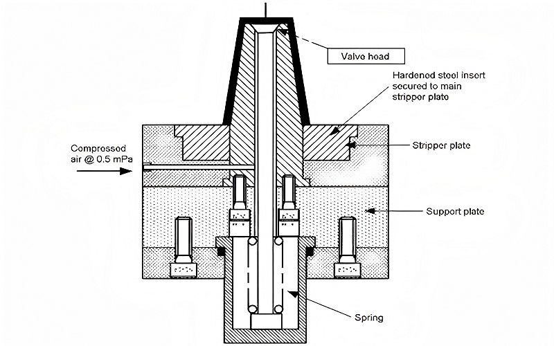
The ejector system is a critical component of injection mold design, responsible for pushing the molded parts out of the mold after cooling. Key points about ejector pins include:
- Ejector pins are commonly used in the ejection system to perform the ejection function.
- Pins should ideally be placed on parts that won’t be visible to avoid cosmetic defects.
- Ejector pins should be positioned away from sloped surfaces to ensure effective ejection.
Using a robust ejector mechanism is crucial for maintaining consistent performance during the ejection process. To prevent deformation of the part during ejection, it’s important to distribute the ejection force evenly across the part. This careful placement and distribution of ejector pins are essential for maintaining the quality and integrity of the injection molded part.
The design of the ejector system is crucial in the injection molding process. Proper placement and distribution of ejector pins ensure smooth and efficient part ejection. Next, we’ll discuss material shrinkage compensation.
Material Shrinkage Compensation
Material shrinkage is a common phenomenon in injection molding, necessitating careful design to compensate for the reduction in size of molded parts as they cool. Different resins have varying shrinkage properties, requiring tailored mold designs for each material type. Managing cavity pressure is essential, as increased pressure can help reduce shrinkage.
Mold conditions and melt temperature can have a significant impact on material shrinkage. These factors play a crucial role in the final outcomes of the material. Controlling these factors helps designers minimize shrinkage and achieve more accurate part dimensions. Understanding the specific shrinkage properties of the plastic material and the effects of melted plastic is key to designing high-quality molds.
In conclusion, material shrinkage compensation is an important aspect of injection mold design. By carefully managing cavity pressure and temperature, designers can reduce shrinkage and ensure the accuracy and quality of the final product.
Next, we’ll explore surface finishes and textures, which play a significant role in the appearance and functionality of injection molded parts, including flat surface options.
Surface Finishes and Textures
Surface finishes and textures significantly influence the cosmetic appearance and functional characteristics of injection molded parts. The surface of the molded part reflects the mold’s surface quality, making it essential to choose the right finish and texture for the desired outcome. Textures and polishes are often defined by trade associations and companies, known as SPI finishes and Mold Tech textures.
Texturing in mold design provides multiple benefits, such as improving grip, camouflaging imperfections, and reducing wear. Textured mold surface also enhances adhesion for paints and stickers, which is crucial for both aesthetic and functional reasons. The material selected for the part impacts the achievable surface finish, as different materials respond differently to finishing techniques.
Injection speed and temperature play key roles in determining the surface finish quality:
- Faster injection speeds generally lead to smoother finishes.
- Steel molds offer a wider variety of surface finishing options compared to aluminum molds because they can be polished more effectively.
- Utilizing mold flow simulation helps identify how material choices affect surface finish and potential defects before production.
Surface finishes and textures are crucial for both the appearance and functionality of parts. Careful selection of finish and texture enhances the product’s aesthetic appeal and performance. Next, we’ll address common defects and prevention strategies in injection molding.
Common Defects and Prevention Strategies
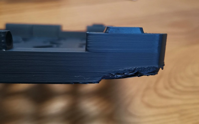
Injection molding, while highly efficient, is not without its challenges. Common defects include:
- Sink marks: Depressions that form when internal material shrinks, pulling the outer layer inward.
- Warping: Occurs due to uneven cooling, causing different areas of a part to shrink at varying rates.
- Knit lines: Appear as discolorations from merging flows, affecting aesthetics and reducing part strength. Designing knit lines away from high-stress areas can minimize defect occurrences. Additionally, addressing sink mark issues can improve overall part quality.
Short shots happen when the mold isn’t completely filled with material, leading to incomplete parts. Burn marks, caused by trapped air overheating during injection, are another common issue. Delamination occurs when layers of a molded part separate due to material contamination. Implementing shrinkage compensation in the same mold cavities can counteract the expected material contraction after cooling.
Key factors for achieving accurate part dimensions and mold design include:
- Using materials with low shrinkage tendencies, such as certain amorphous polymers.
- Designing a well-crafted mold that accurately accommodates resin behavior, significantly reducing post-processing needs.
- Implementing an effective venting system to release air from the mold as it fills with molten plastic, preventing vacuum formation and potential defects.
Addressing these common defects and implementing effective prevention strategies ensures the production of high-quality parts.
Prototyping and Testing
Prototyping and testing are essential phases in the injection molding process, allowing for early identification of manufacturing issues and reducing risks before large-scale production. A well-executed prototyping phase helps maintain project timelines and budgets by identifying potential design flaws early. Prototyping enables visualization of the product’s functionality and assembly, ensuring design intentions are met.
Effective prototyping can lead to continuous improvements in product design through iterative testing. The prototyping process fosters trust between manufacturers and clients, enhancing collaboration and communication. By addressing potential issues during the prototyping phase, designers can make necessary adjustments and ensure the final product meets quality standards.
In the automotive industry, for example, prototyping plays a critical role in validating design choices and ensuring the safety and reliability of components. Technologies like 3D printing and CNC machining, including NASA assembly CNC machining, are often used in prototyping to produce accurate representations of the final product. These prototypes can then be tested for functionality, durability, and performance, providing valuable insights before committing to full-scale production.
Prototyping and testing are indispensable steps in the injection molding process. Identifying and addressing potential issues early ensures the production of high-quality parts and maintains manufacturing efficiency and cost-effectiveness. Next, we’ll explore cost considerations in mould design.
Cost Considerations in Mould Design
Cost considerations are a crucial aspect of injection mold design, as they can significantly impact the overall budget of an injection molding project. Key points include:
- The typical cost range for custom molds used in injection molding is $3,000 to $100,000+.
- The complexity of the mold generally increases the costs.
- Tooling costs can account for 50-70% of overall costs for smaller production runs.
Using side-action cores in molds can increase production costs by 15% to 30%, with a minimum additional tooling cost of $1,000 to $1,500. Common materials for manufacturing molds include aluminum or tool steel, each with different cost implications based on their properties. Using molds made from harder metals can significantly raise costs, especially for parts requiring a smooth finish.
Key factors to consider in mold manufacturing include:
- The expected lifespan and durability of the mold should align with the production volume to optimize material choice.
- The complexity of a mold directly affects production time and cost, as intricate designs require more precise machining in the manufacturing process.
- Selecting the right mold manufacturing partner can influence overall costs based on their experience and technology.
Cost considerations in mold design are multifaceted and require careful planning. Understanding the factors that influence costs and making informed decisions helps designers create cost-effective molds. Let’s wrap up our discussion with a summary and conclusions.
Summary
In conclusion, successful injection molding hinges on meticulous mould design. From understanding the importance of draft angles and wall thickness to managing undercuts and optimizing gate placement, each element plays a crucial role in producing high-quality injection molded parts. Effective cooling and ejector system designs further enhance the efficiency and quality of the molding process.
By carefully considering material shrinkage, surface finishes, and potential defects, designers can create molds that deliver consistent, high-quality results. Prototyping and testing are essential for identifying and addressing issues early, ensuring that the final product meets all design and functional requirements. Cost considerations are also critical, requiring a balance between quality and budget.
Armed with the knowledge from this comprehensive guide, designers can confidently approach their injection molding projects, optimizing mould design for superior performance and cost-effectiveness. The journey to mastering injection molding is continuous, but with each project, you will refine your skills and achieve greater success.
Frequently Asked Questions
Why is early involvement of an injection molder crucial in the design process?
Early involvement of an injection molder is crucial to identify and resolve design challenges, ensuring efficient filling and cooling of the molten plastic. This proactive approach leads to smoother production cycles and enhanced quality of the final molded parts.
What are the benefits of maintaining uniform wall thickness in injection molded parts?
Maintaining uniform wall thickness is crucial as it ensures consistent cooling, reduces the risk of defects like warping and cracking, and enhances the overall quality of the final product. This practice ultimately leads to improved performance and durability of injection molded parts.
How do cooling channels impact the injection molding cycle?
Cooling channels significantly enhance part quality and reduce cycle time in injection molding by regulating temperature and preventing defects like warping and uneven shrinkage. Therefore, their design is crucial for optimal production efficiency.
What are common defects in injection molding, and how can they be prevented?
Common defects in injection molding such as sink marks, warping, and burn marks can be effectively prevented by ensuring proper mold design, managing cavity pressure and temperature, and implementing efficient venting systems. Addressing these factors is crucial for producing high-quality molded products.
How does prototyping benefit the injection molding process?
Prototyping significantly benefits the injection molding process by facilitating early identification of manufacturing issues, thereby reducing risks associated with large-scale production. This approach not only helps maintain project timelines and budgets but also enables continuous improvements through iterative testing.