How can you design plastic parts that perform well in injection molding?
This guide explores critical aspects like wall thickness, draft angles, and material selection.
Master these principles to ensure your parts are high-quality and durable. Read on to uncover the essentials of plastic design for injection molding.
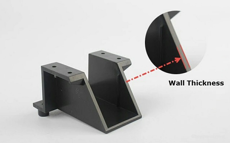
Importance of Wall Thickness in Injection Molding
Wall thickness greatly impacts the functionality, durability, and quality of injection molded parts. Improper wall thickness can lead to stress, causing warping, sink marks, cracking, and premature failure of injection molded parts manufactured using an injection molding machine with hot tip gates.
Maintaining consistent wall thickness promotes uniform cooling, which reduces defects and enhances overall wall thickness quality.
For example, maintaining a boss thickness between 40-60% of the base wall thickness helps prevent defects, ensuring a robust and reliable product when manufacturing plastic parts.
Uniform Wall Thickness
Uniform wall thickness helps prevent defects such as sink marks and warping, and ensures consistent material flow and cooling.
To achieve uniform wall thickness, uniform flow and uneven wall thickness can create pressure spikes and material degradation, leading to poor process control and further defects.
Thicker walls cool slower than thinner walls, increasing cooling time and potentially causing warping due to stress buildup in uneven sections.
Prioritizing uniform wall thickness and addressing issues related to thin walls, along with ensuring proper wall thickness and considering vertical walls, is key to improving part performance and quality when produce plastic parts.
Transitions and Corners
Smooth transitions and rounded corners are essential in injection molding design to minimize stress and defects.
Sharp corners in plastic parts can cause stress concentrations, compromising structural integrity, which material suppliers often highlight as a key concern. Using rounded corners helps enhance part durability by minimizing these stress concentrations.
Additionally, smooth transitions between varying wall thicknesses are crucial as they reduce stress during the cooling phase, especially when considering mold separate processes.
Adding radii to the corners ensures consistent plastic flow, maintains even wall sections, and avoids potential cracking.
Draft Angles for Effective Mold Release
Draft angles are crucial in injection molding as they prevent damage and reduce resistance during part ejection. Incorporating draft angles facilitates the release of parts from the mold after cooling, minimizing risks during ejection.
By reducing friction during part release, draft angles help prevent damage and ensure the part retains its intended shape and dimensions.
Careful consideration of the mold’s draw and separation ensures smooth and efficient part ejection when setting draft angles.
Recommended Draft Angles
Generally, a draft angle of 1½ to 2 degrees is needed for most parts with depths up to 2 inches.
For parts with highly polished outer walls, a smaller draft angle between 1/8 to 1/4 degree is recommended to prevent drag marks, often enhanced by using sub gates.
A typical minimum draft angle of 1/2 to 1 degree ensures easy ejection without compromising part integrity, especially when dealing with manually trimmed gates.
Textured parts require an additional draft of 1.5 degrees per thousandth-inch of texture depth to prevent scraping and drag marks.
Impact on Dimensional Accuracy
Draft angles significantly impact the dimensional accuracy of injection molded parts. Small features require draft angles to prevent sticking during ejection and minimize the risk of cracking.
For parts with significant shrinkage or complex shapes, larger draft angles should be considered to facilitate proper ejection.
Textured surfaces need increased draft compared to smooth surfaces to prevent scraping and drag marks during ejection. Additionally, the positioning of gates can influence the quality, affecting fill balance and cooling.
Designing with Ribs and Bosses
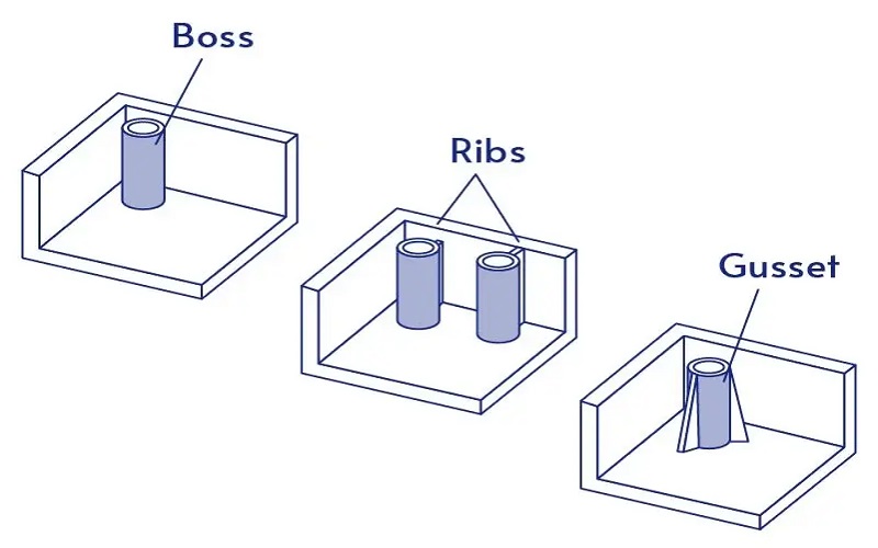
Ribs and bosses significantly enhance the strength and functionality of injection molded parts. Ribs should typically have a thickness that is 40-60% of the base wall thickness to maintain overall structural integrity.
Bosses are used to support assembly and increase the structural integrity of injection molded parts. Proper design of ribs and boss feature ensures robust parts that can withstand various stresses and loads.
Optimal Rib Design
Ribs provide structural integrity to injection molded parts.
They also enhance the load-bearing capacity. Strategically placed support ribs can enhance strength and rigidity in plastic parts without negatively impacting production speed.
Rib thickness should not exceed 60% of the nominal wall thickness to avoid defects, especially as plastic shrinks during cooling.
The maximum height of ribs should be less than five times the thickness of the base material to ensure successful molding, considering the outer diameter of the part. Additional draft on small and deep ribs can improve their ejection from the mold.
Boss Placement and Integration
Bosses are used for assembling products, locating, or mounting other components, enhancing the functionality of injection molded parts.
Integrate bosses by connecting them to outer walls or using them with ribs to avoid thick wall sections.
Hollow bosses have the following design considerations:
- They can accommodate fasteners such as screws and dowel pins.
- The recommended depth for bosses with blind holes should not exceed three times the diameter of the hole.
- The base of the boss must have a fillet radius.
- This fillet radius should be between 0.4 and 0.6 times the thickness of the base material.
Material Selection for Injection Molding
Material selection is a critical aspect of injection molding, with the material properties of a plastic determining its suitability for various applications, such as those involving self tapping screws.
The composition of polymer chains affects the performance and suitability of plastics. Semi-crystalline plastics, with their random sections of crystalline structures, provide good bearing surfaces, living hinges, and good chemical resistance.
Amorphous plastics tend to shrink and warp less compared to semi-crystalline plastics, making them more predictable in behavior. Engineers focus on high-performance plastic resin to ensure optimal material choices for specific molding applications.
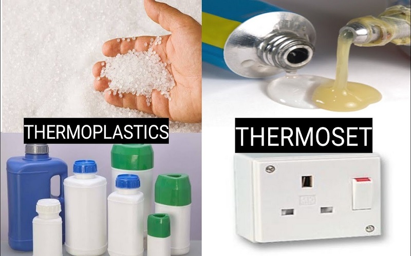
Thermoplastics vs. Thermosets
Thermoplastics can be reprocessed multiple times without undergoing a chemical change during molding. When heated, thermoplastics become soft and easy to mold.
Common types of thermoset plastics are:
- Epoxy
- Silicone
- Polyurethane
- Phenolic
Thermosets undergo a chemical reaction that forms irreversible bonds during processing, making them stable at high temperatures. Unlike thermoplastics, regrind usage is impossible with thermoset plastics due to their irreversible process.
Reinforced Plastics
Reinforced plastic material can significantly enhance mechanical properties and performance by incorporating materials like glass fibers.
These reinforced materials provide greater structural integrity, making them ideal for applications requiring high strength and durability.
The use of reinforced plastics in plastic injection molding can also reduce deformation during cooling, resulting in higher quality plastic part.
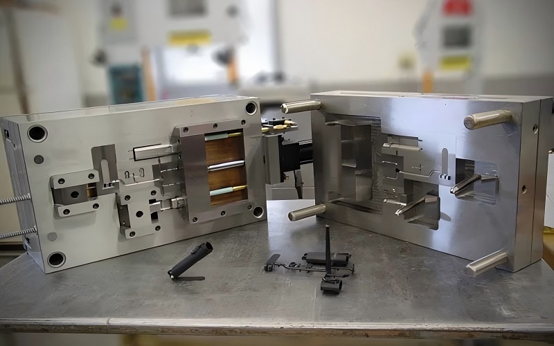
Managing Parting Lines and Ejector Pins
The first consideration when designing an injection mold is selecting the parting line. The parting line is crucial for determining the separation of mold halves after an injection cycle.
During the injection mold design process, the melt flows towards the parting line, making its placement vital for the quality of the final product. An injection molder plays a significant role in this process, particularly in the overall mold design.
The direction of the line of draw must be decided during parting line selection to ensure smooth mold operation. The a and b sides of the mold ensure that the parts stay on the ejection side after production.
Optimal Parting Line Placement
Parting lines in designs such as LEGO bricks are typically located along the bottom edges. Placing parting lines on sharp edges simplifies mold construction and reduces costs.
However, parting lines should avoid being placed on filleted surfaces to prevent visibility issues, ensuring a clean and aesthetically pleasing final product.
Ejector Pin Guidelines
Ejector pins should be positioned on surfaces that are not visible to prevent marks on the finished part. Proper placement of ejector pins can significantly reduce the risk of surface marks on visible areas of the molded part.
Careful ejector pin placement is vital for maintaining the aesthetic quality of the molded part and ensuring the proper function of the core pin.
Gates and Their Role in Injection Molding
Gates are openings used for the purpose of allowing molten plastic to enter the mold’s cavity. Tunnel gates play a crucial role in the molding process.
The function of a gate in injection molding is to direct molten plastic into the mold cavity, ensuring a consistent and controlled flow of material.
Effective gate design and placement optimize the injection molding process and ensure high-quality parts.
Common Gate Designs
The most common gate design in injection molding is the edge gate. Edge gates are preferred for their simplicity and effectiveness in providing good flow and minimal defects.
Other gate types include direct sprue, fan, and pinpoint gates, each tailored for specific applications such as thin-walled parts or areas requiring precise filling.
Gate Location Considerations
Optimal gate placement aims to minimize flow distance and enhance the cosmetic appearance of the finished part. Choosing the correct gate location optimizes the manufacturing process and improves the flow path dynamics. Proper gate placement reduces the likelihood of defects such as air traps and weld lines, ensuring a high-quality final product.
When choosing gate locations, consider factors like part geometry, material characteristics, and the desired finish quality.
Preventing Common Defects in Injection Molding
Preventing common defects in injection molding starts with proper design. Key considerations include:
- Appropriate wall thickness reduces the risk of defects like sink marks and warping.
- Uneven wall thickness during cooling can lead to warping, twisting, or cracking.
- Thick sections cooling too slowly can lead to inward pulling, creating stresses, sink marks, or voids.
It’s easier to avoid defects at the design stage rather than during processing. Common defects in injection molded parts are often caused more by part processing than by injection molding processes.
Avoiding Sink Marks
Thick wall sections can lead to sink issues in injection molded parts. Thick ribs are prone to shrinkage and may cause sink marks on the opposite side.
Core out solid sections or use cross-hatched rib patterns to avoid sink marks and prevent sink marks.
Addressing Warping and Shrinkage
Uniform wall thickness prevents defects like sink marks and warping, ensuring consistent material flow and cooling. Selecting appropriate plastic materials is crucial for minimizing shrinkage and warping during cooling.
Using reinforced plastics, such as those with glass fibers, can help enhance the mechanical properties and reduce deformation during cooling. Effective cooling strategies and methods significantly reduce the risk of warping and shrinkage in injection molded parts.
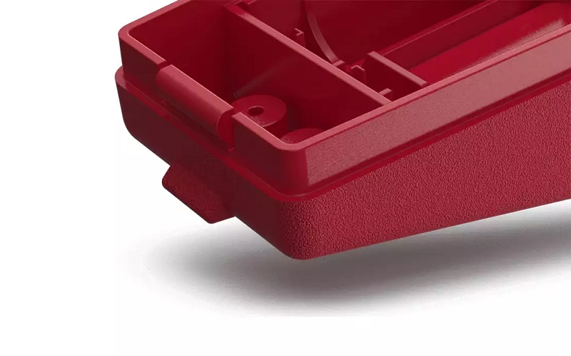
Surface Finish and Texturing
The characteristics of the mold surface directly influence the final appearance and texture of the molded plastic component. Molding surfaces are created through techniques such as:
- CNC machining
- Grinding
- EDM
- Turning
Parting lines should ideally be placed on less visible surfaces to enhance the aesthetic appeal of the final product. The purpose of creating a texture on molded parts is to ensure surface consistency and impact part design.
Matching the texture of sample parts to the specified light, medium, or heavy texture in the design is vital for achieving the desired finish.
Achieving Desired Surface Texture
Methods to achieve surface textures for molded parts include acid etching, laser engraving, and CNC machining.
The mold maker typically prepares the surface for texturing in the mold production process, including mold building.
Many molders choose to outsource the texturing aspect of tool building due to specialized surface finishes being common in other industries.
A useful guideline for creating draft angles suggests:
- Adding 1.5 degrees of draft for every 0.001” of texture finish depth.
- Ensuring surface texturing has a minimum draft angle to facilitate easier part ejection.
- Using the draft angle to avoid surface damage.
Enhancing Cosmetic Appearance
Surface finish and texturing play a vital role in determining the aesthetic quality of injection molded parts, influencing both their marketability and consumer perception.
Different methods, including polishing, painting, and using textured molds, can be employed to achieve smooth or textured finishes depending on the desired effect.
Proper parting line placement manages weld lines and minimizes their visibility, enhancing the overall appearance of the molded part.
To ensure optimal cosmetic appearance, it is essential to combine good design practices with appropriate ultrasonic welding techniques.
Snap-Fit Connections and Interference Fits
Snap-fit connections allow for efficient assembly by engaging components without the need for additional fasteners.
A snap-fit assembly involves snapping parts together without additional fasteners, relying on elastic deformation to lock parts together when pushed past an obstacle.
Materials like polypropylene and polyethylene are recommended for living hinges due to their elasticity. For repeated function, clips must be designed to prevent fatigue over time.
Types of Snap-Fit Connections
Cantilever snap-fits are widely used for their simplicity and effectiveness in various applications. Annular snap-fits create a circular locking mechanism, providing a secure connection between parts.
It’s essential to consider the material’s elasticity and stress when designing snap-fit connections.
Snap-fit connections are critical for efficient assembly in plastic parts, providing quick and effective joining methods.
Designing Interference Fits
Interference fits are designed to create a tight connection between parts, ensuring that they remain assembled during use. The interference amount in a fit is influenced by the manufacturing tolerances of the components.
Properly designed interference fits can improve the structural integrity of plastic assemblies.
Summary
Mastering plastic design for injection molding involves a delicate balance of various factors, from wall thickness and draft angles to material selection and surface finishes.
By understanding and implementing the principles outlined in this guide, designers can create high-quality, durable, and aesthetically pleasing injection molded parts.
Embrace these best practices, and you will be well on your way to producing exceptional plastic components that meet and exceed industry standards.