
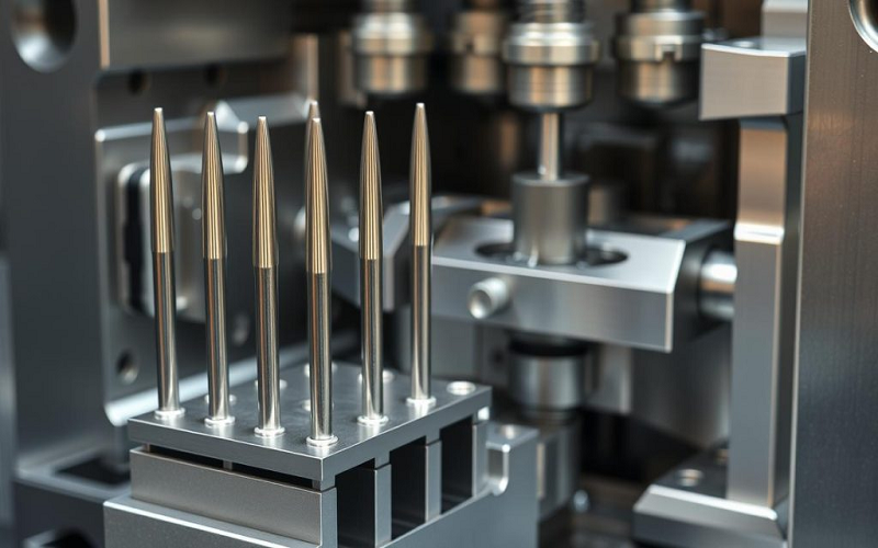
Injection molding ejector pins are indispensable components in the injection molding process, responsible for smoothly ejecting the cooled plastic molded parts from the mold.
The design and arrangement of ejector pins directly affect the quality of the finished product and production efficiency. Proper selection and layout of ejector pins can not only effectively prevent molding defects but also reduce ejector pin marks on the product’s appearance.
This article will delve into the types and design considerations of injection molding ejector pins, as well as common ejection defects and their solutions, helping engineers and mold designers better understand and apply ejector pin technology to enhance the performance of injection molds and the quality of finished products.
What Are Injection Molding Ejector Pins?
Injection molding ejector pins are precision components used in the injection molding world to push molded plastic parts out of the mold cavity after the plastic has cooled and solidified.
The injection molding process involves clamping the mold, injecting molten plastic, cooling, and then opening the mold.They are key components of the mold’s ejection system, ensuring that parts can be smoothly and efficiently released during the injection molding cycle.
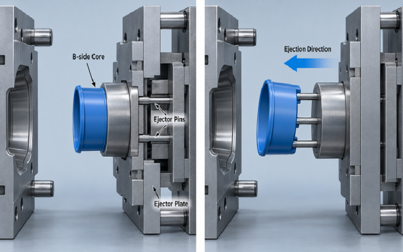
The injection mold typically consists of two halves: the A side (the cavity side) and the B side (the core side). Ejector pins are located on the B side mold half, where the molded part remains after the mold opens.
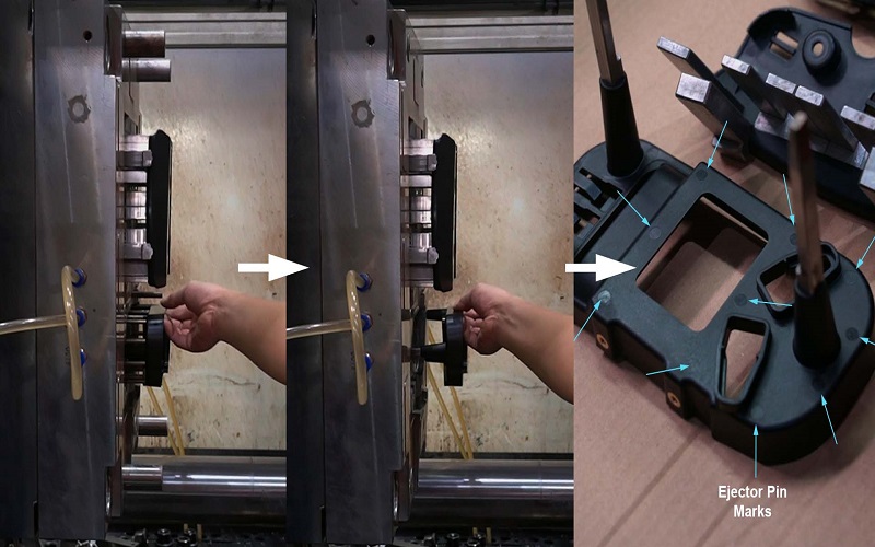
When the mold opens, the ejector pin pushes the cooled plastic part out of the mold cavity by extending through ejector pin holes in the mold. This mechanical action is essential for maintaining production speed and preventing damage to delicate molded parts.
Additionally, ejector pins must withstand high temperatures and mechanical stress throughout the injection molding process.
Materials such as case hardened pins, through hard ejector pins, and black ejector pins are selected based on their ability to withstand temperatures ranging from 200°C to 1000°C and resist wear over many cycles.
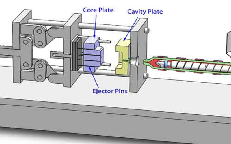
What Is The Role Of Ejector Pins In Injection Molding?
Their placement, or pin placement, within the mold cavity is carefully planned to optimize ejection force and minimize surface defects such as ejector pin marks, which are small circular dents left on the part surface due to the pin’s contact.
The ejector pin channel guides the pins as they move, ensuring precise pin movement during the ejection process. The pins extend forward to push the part and then retract to allow the mold to close again for the next injection molding cycle.
Ejector plates drive the pins forward, and ejector blocks or ejector pads may be used to distribute force and prevent marks, especially on thin or contoured surfaces.
Understanding the role and design of injection molding ejector pins is essential in the injection molding world to ensure smooth ejection, prevent surface defects, and maintain high-quality production output.
Material Selection for Injection Molding Ejector Pins
The material selection for injection molding ejector pins is crucial to ensure the durability of the pins and the quality of the molded parts.
Ejector pins must withstand high temperatures, high pressure, and frequent mechanical impacts, so it is important to choose high-quality materials that are wear-resistant and have excellent heat resistance.
- Tool Steel: Common tool steels include H13 steel, which, after nitriding treatment, significantly improves surface hardness while maintaining internal toughness, making it suitable for high-temperature environments.
- High-Speed Steel(SKD61, SKH51): This steel is surface-nitrided to form a very hard surface layer, significantly enhancing the wear resistance and corrosion resistance of the ejector pins.
- Black Coated Steel: Ejector pins made of black coated steel undergo special surface treatment to provide self-lubricating properties, reducing friction and wear while enhancing high-temperature performance.
Therefore, ejector pin materials are usually selected from high-quality tool steels, which undergo nitriding or quenching treatments to enhance wear resistance and heat resistance. Surface treatments such as black coating can reduce friction and extend the service life of the ejector pins.
The choice of material needs to consider the characteristics of the molding material and the working temperature to ensure that the ejector pins maintain stable performance under high temperature and high pressure conditions.
Types Of Ejector Pins Used DuringInjection Molding Process
Different types of ejector pins include standard round pins, blade pins, and ejector sleeves, each designed to meet specific requirements based on part geometry, material, temperature, and mold design.
Round Ejector Pins
These are the most widely used ejector pins characterized by their cylindrical shape with a flat or slightly rounded pin end. Round ejector pins provide reliable ejection force and are suitable for most general molding applications. They push directly against the molded part to release it from the mold surface.
Through Hard Ejector Pins
Through hard pins are heat-treated throughout their entire cross-section, offering uniform hardness and strength. They can withstand working temperatures up to 200°C and are commonly used in standard thermoplastic injection molds. Their durability prevents bending and wear during repeated cycles.
Case Hardened Ejector Pins
Also known as Nitride H13 pins, these ejector pins have a hardened surface layer achieved through nitriding, providing enhanced wear resistance and the ability to operate at temperatures above 200°C, up to around 600°C. They are preferred for molds handling engineering plastics or semi-crystalline materials.
Black Ejector Pins
Black ejector pins feature a self-lubricating surface treatment enabling them to withstand extreme temperatures up to 1000°C. These pins are ideal for demanding applications such as metal molds or automotive parts molding, where high thermal resistance and reduced friction are critical.
Ejector Sleeves
Ejector sleeves are hollow cylindrical pins designed for ejecting round or tubular parts. They consist of an outer sleeve and an inner core pin, allowing the molded part to be pushed evenly without deformation. Ejector sleeves help prevent ejector pin marks on delicate or thin-walled parts.
Contoured Pins
Contoured ejector pins are custom-shaped pins ground to match the contour of the molded part surface. These pins are used when the ejection surface is not perpendicular to the pin movement direction, allowing more precise and gentle ejection to prevent cosmetic damage.
Ejector Blades
Ejector blades are flat, blade-like pins used to eject parts with thin walls or complex geometries. They provide a broader contact area to distribute the ejection force and reduce the risk of deformation or pin marks.
Position Pins
Position pins help align mold components during closing and are sometimes integrated with ejector systems to ensure precise mold half alignment and smooth ejection.
Through Hard Pins
Through hard pins, as mentioned, maintain uniform hardness and are suitable for moderate temperature applications. They are often used where consistent strength and wear resistance are required.
Each ejector pin type plays a specific role in ensuring efficient, defect-free ejection of molded parts. Selecting the right ejector pin type, considering material, temperature, and part design, is essential for optimizing mold performance and product quality.
| Part Feature | Recommended Diameter | Preferred Type | Notes |
|---|---|---|---|
| Thin walls (< 1 mm) | ≥ 1.5 mm | Blade / flat pin | Higher contact area |
| Standard walls (1–2.5 mm) | 2–4 mm | Round pin | Most common |
| Thick walls / deep features | 3–6 mm+ | Round or sleeve | Higher strength |
| Tall/thin bosses | Matching boss ID | Sleeve (tubular) ejector | Prevents boss cracking |
| Narrow deep ribs | — | Blade ejector | Better support than small round pins |
| Precision / micro parts | 0.8–1.5 mm | Stepped / shouldered pin | Requires good guidance |
Design Considerations for Injection Molding Ejector Pins
Ejector systems must be designed to ensure reliable and repeatable part removal. Ejector pins need to maintain tight tolerances to prevent flash or plastic leakage. Proper ejector pin placement, size, and type are critical for optimal mold performance and part quality.
Ejector Pin Placement And Pin Locations
Ejector pin placement is a fundamental design consideration. Pins should be strategically located to provide uniform ejection force across the part, preventing warping or localized stress.
Pin locations are typically chosen to avoid visible cosmetic surfaces and to push against thicker or reinforced areas such as ribs or bosses, which can withstand the mechanical force without deformation.
Symmetrical distribution of pins helps maintain part integrity and reduces the risk of distortion during ejection.
Ejector Pin Size and Quantity
The diameter and number of ejector pins directly affect the distribution of ejection force. More or wider pins can reduce the force exerted by each pin, minimizing the chance of pin marks or part damage.
However, increasing the number or size of pins can also complicate mold design and increase cost. Designers must balance these factors based on part geometry and material properties.
Ejector Pin End Configuration
The shape of the ejector pin end influences how force is applied to the part. Flat end pins are common for direct ejection on flat surfaces, providing even contact and minimizing surface damage.
Raised ejector pads or slightly recessed pads can be used to match contoured surfaces or to avoid creating visible marks. Contoured pins or pads raised slightly above the part surface help distribute force on curved or angled surfaces, reducing cosmetic defects.
Draft Angles and Surface Texture
Incorporating draft angles of 1° to 3° on molded parts facilitates easier release from the mold and reduces the risk of pin marks.
The required ejection force is influenced by part shrinkage, contact area, and surface texture; smooth surfaces are more prone to visible ejector pin marks, so pins are often placed on less visible or textured areas. Such surfaces tolerate the slight marking better without compromising appearance.
Use Of Raised Ejector Pads And Edge Gates
Raised ejector pads provide a dedicated area for pins to push against, especially on thin or ribbed sections where direct pin contact might cause damage.
An edge gate, which is a gate located at the edge of the part, can reduce the visibility of gate and ejector pin marks by directing flow and ejection forces away from cosmetic areas.
Rib Edges and Clip Side
Rib edges can provide additional surface area for ejector pins to push against, improving ejection effectiveness. In designs with clips, the clip side of the part may require special ejector pin arrangements to ensure smooth release without cosmetic damage.
Secondary Operations And Post Gate Design
In some cases, a post gate allows resin to be injected through an ejector pin hole, forming a raised ejector pad or post on the part. This post is often removed in a secondary operation to improve part aesthetics. Designers must consider this when planning ejector pin placement and mold design.
Effective ejector pin design balances functional requirements with cosmetic considerations. Proper ejector pin placement, pin size, end configuration, and material selection all contribute to smooth part ejection, reduced defects, and longer mold life.
For materials like liquid silicone rubber, ejector pins are often not used because of the material’s softness; parts are typically manually removed.
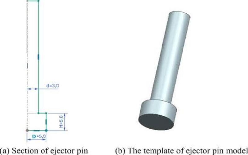
Common Defects Caused By Ejector Pins During The Injection Molding Process
Ejector pins, while essential for part ejection, can sometimes cause defects if not properly designed or used. Understanding these common defects helps in optimizing ejector pin design and injection molding parameters to minimize their impact.
Ejector Pin Marks
Ejector pin marks are the most common defect associated with ejector pins. These marks appear as small circular dents or impressions on the surface of the molded part where the pin contacts the plastic.
While often unavoidable, improper pin placement, excessive ejection force, or insufficient draft angles can exacerbate their visibility.
These marks not only affect the cosmetic appearance but can also increase internal stress at the pin mark locations, potentially leading to cracking or reduced part strength.
Part Deformation or Warping
If ejector pins are unevenly distributed or too few in number, the ejection force may be concentrated in limited areas, causing the part to warp or deform during ejection. Using more pins can distribute ejection force more evenly, reducing the load on individual pins and minimizing the risk of damage.
Pin Breakage
Ejector pins can break if subjected to forces beyond their mechanical strength, often due to improper pin diameter, length, or material selection. Breakage leads to production downtime and mold damage, increasing maintenance costs.
By carefully considering ejector pin design and placement, many common defects can be minimized, ensuring high-quality molded parts with efficient production cycles.
Conclusion
Injection molding ejector pins are critical components that directly impact the efficiency of part ejection and the quality of the finished product.
Proper selection of ejector pin types, materials, and precise design considerations such as placement, size, and end configuration are essential to minimize defects like ejector pin marks and part deformation.
Incorporating features like draft angles, raised ejector pads, and symmetrical pin distribution further enhances ejection performance and mold longevity.
By understanding and applying these principles, engineers and designers can optimize injection molding processes to achieve high-quality, defect-free parts while maintaining production efficiency and reducing maintenance costs.