
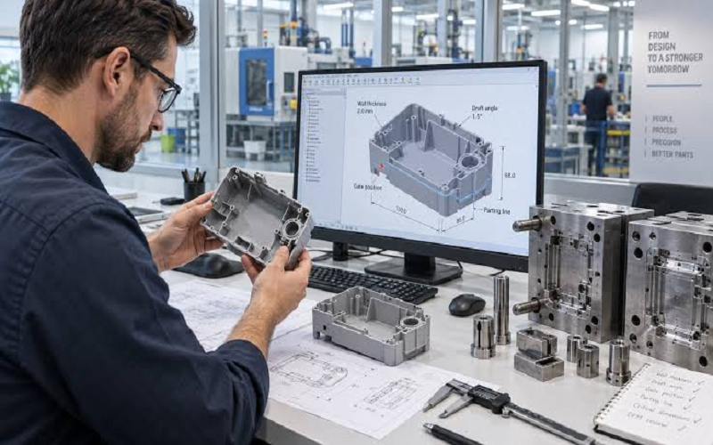
Plastic part design is a crucial aspect of the injection molding process, directly impacting the product’s functionality, manufacturing efficiency, and cost control.
A well-considered design not only ensures the structural strength and aesthetic quality of the plastic part but also effectively prevents manufacturing defects such as sink marks, warping, and difficulties in demolding.
This article will introduce key principles and practical tips for plastic part design, helping you fully consider material properties, mold structure, and manufacturing processes during the product design phase to achieve high-quality and efficient plastic product development.
Whether you are a product designer, structural engineer, or involved in procurement and manufacturing coordination, you will find valuable references here.
Why Proper Plastic Part Design Matters For Injection Molding ?
In injection molding, the design of plastic parts is not simply about “drawing the shape”; it directly determines the cost, efficiency, and quality performance of the entire subsequent manufacturing process.
Every decision made during the design phase is exponentially reflected in mold costs, production cycles, part yield, and final product performance.
Impact On Mold Cost
First, the design has the most direct impact on mold costs. Proper wall thickness, draft angles, fillets, and rib designs can significantly simplify mold structures, reducing the need for complex mechanisms like sliders, lifters, and forced ejection, thereby lowering mold machining difficulty and expenses.
Conversely, if there are issues such as abrupt changes in thickness, sharp internal corners, or lack of draft angles in the design, molds often require additional mechanisms or repeated mold repairs later, resulting in substantial increases in mold costs or even mold scrapping and remaking.
Impact On Production Cycle
Second, design quality directly affects the production cycle. Good design enables smooth material flow, uniform cooling, and easy demolding, thus shortening molding cycles and increasing output per mold.
Poor design can cause filling difficulties, excessive cooling time, and demolding jams, slowing down production rhythm and forcing delivery delays.
Impact On Part Quality
Furthermore, part quality and yield heavily depend on design. Uneven wall thickness easily leads to shrinkage, warping, and internal stresses; insufficient draft angles cause scratches or ejector marks; sharp corners tend to create stress concentrations and cracks.
These issues not only reduce yield but also increase rework and scrap costs. In practice, many projects’ high defect rates can be traced back to ignoring injection molding process constraints during design.
Therefore, fully considering injection molding process characteristics early in design is the most effective way to control costs, shorten delivery times, and improve quality and yield.
Using CAD files and simulation tools, designers can predict potential manufacturing difficulties and make informed decisions early in the project.
Plastic Part Design Steps For Injection Molding
The specific steps for designing plastic parts include several key stages to ensure that the designed plastic components meet functional requirements while maintaining good manufacturability and cost-effectiveness.
- Requirement Analysis and Specification Definition: Before design, it is necessary to clarify customer needs and the functional specifications of the plastic part, including the usage environment, mechanical performance, size constraints, and appearance requirements, forming detailed design specifications.
- Preliminary Design and Concept Validation: Design validation and testing are essential steps before mass production. Based on requirements, sketches and 3D models are created to determine the basic shape and structure, conduct design validation and testing, and use prototypes to identify potential issues.
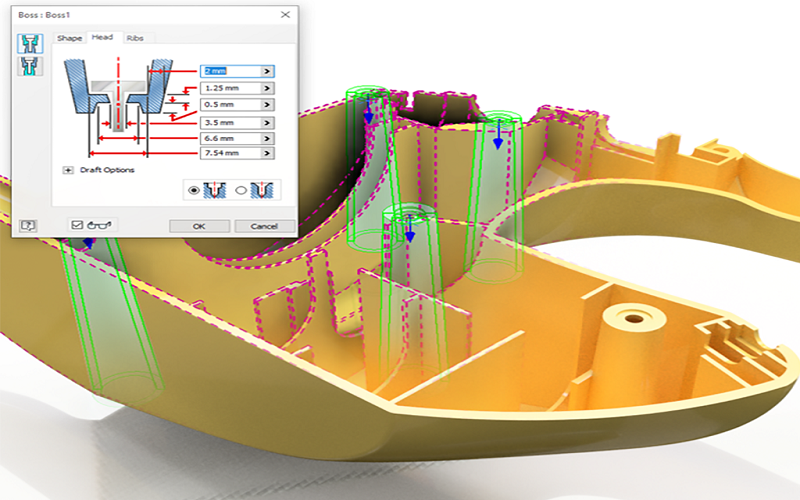
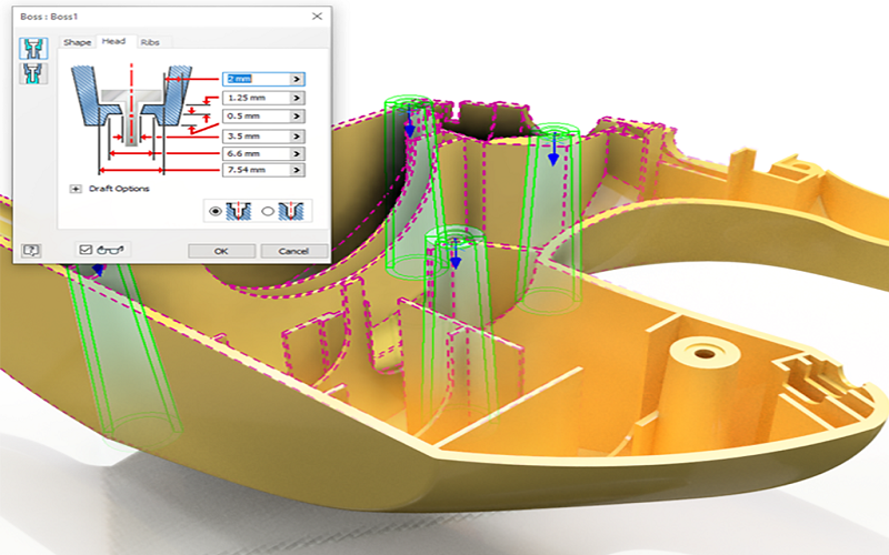
- Structural Optimization and Design Refinement: Adjust uniformity of wall thickness, design reinforcing ribs, set appropriate draft angles, apply fillets to reduce stress, and optimize gate and runner layout.
- CAE Simulation Analysis: Use mold flow analysis to predict filling defects, employ finite element analysis to evaluate stress and deformation, and optimize the design.
- Prototype Fabrication and Design Verification: Produce physical samples using rapid prototyping technologies such as 3D printing to verify dimensions and functions, and modify designs promptly.
- Mold Design and Manufacturing Preparation: Determine mold structure, cavity quantity, cooling system, and ejection mechanism, balancing manufacturing difficulty and cost control.
- Mold Trial and Process Adjustment: Conduct trial molding to inspect part appearance and dimensions, adjust process parameters, and ensure smooth mass production.
- Quality Control and Continuous Improvement: During mass production, apply statistical process control and quality inspection, feedback to optimize design and process, and enhance product competitiveness.
Through these systematic design steps, plastic parts can meet both functional and aesthetic requirements while achieving efficient manufacturing and cost control, laying a solid foundation for successful product launch.
Key Design Principles Of Plastic Products
Designing plastic parts requires a comprehensive understanding of both the material properties and the manufacturing process to ensure optimal performance and manufacturability. Several critical principles should be followed to achieve a successful plastic part design.
Maintain Uniform Wall Thickness
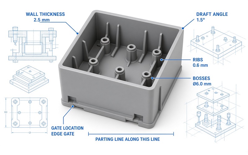
One of the most important considerations in plastic part design is to maintain uniform wall thickness throughout the molded part. Uniform wall thickness helps prevent internal stresses, shrinkage, prevents deformation, and reduces cycle time, which can lead to defects and dimensional inaccuracies.
Generally, the recommended wall thickness for functional plastic parts ranges between 1.5 and 3.5 mm, depending on the plastic material used. For larger components, thicknesses typically range from 2.4 to 3.2 mm, while smaller parts may have wall thicknesses around 1.0 mm.
Incorporate Reinforcing Ribs
To enhance the structural strength of plastic parts without increasing wall thickness, reinforcing ribs are commonly added. These ribs, usually designed to be 0.5 to 0.75 times the wall thickness, provide rigidity and help prevent deformation, especially in large molded parts.
Proper rib design should avoid local material accumulation to prevent shrinkage marks and maintain uniform wall thickness.
Design With Draft Angles
Draft angles typically range from 0.5 to 5 degrees and are designed to reduce friction between the part and the mold, thereby preventing damage during ejection.
The draft angle may vary depending on the plastic material’s shrinkage rate and the surface texture of the part. A draft angle of 1° to 2° per side on vertical walls is recommended to ensure smooth demolding; textured surfaces require larger draft angles of 3° to 5°.
Use Round Corners Instead Of Sharp Edges
Sharp edges concentrate stress and can lead to cracking or premature failure of the molded part. Designing with round corners helps distribute stress more evenly, improves plastic flow during molding, and facilitates easier demolding.
Recommended Formula for Rounded Corners:
- Internal corner radius R ≥ 0.5 × wall thickness
- External corner radius = internal corner radius + wall thickness
However, rounded corners should not be set on the parting line, as this increases the difficulty of mold manufacturing and leaves weld marks on the product surface, affecting its appearance.
Internal corner radii should generally be between 0.5 to 1.5 times the wall thickness, with a minimum radius of 0.3 mm to avoid stress concentration.
Optimize Gate Location
The gate is the entry point where molten plastic flows into the mold cavity, often leaving residual marks on the surface of the part. The gate should be positioned in non-cosmetic areas to control resin flow, reduce weld lines, and ensure uniform packing pressure.
Proper gate location is crucial to ensure even mold filling, minimize weld lines, and reduce residual stress. For complex-shaped or large parts, multiple gates can be used to shorten molding cycles and improve quality. Side gates are suitable for parts with appropriate wall thickness.
Tooling Considerations For Plastic Part Design
Tooling considerations play a vital role in the successful manufacturing of plastic parts. The design of the mold directly influences the production cost, cycle time, and quality of the final product.
When designing plastic parts, it is essential to keep tooling constraints and capabilities in mind to ensure cost-effective and efficient production.
Mold Complexity And Cost
The complexity of the mold impacts the overall tooling cost significantly. Complex molds with features such as sliders, lifters, and side actions increase machining difficulty and maintenance requirements.
Simplifying the mold design by avoiding unnecessary undercuts and designing parts in such a way that they can be ejected easily reduces mold complexity and associated expenses.
Material Selection for Molds
Mold materials commonly include steel, aluminum, and sometimes silicone for prototyping. Steel molds are durable and suitable for high-volume production, capable of withstanding over 500,000 cycles, but are expensive due to machining and heat treatment.
Aluminum molds offer a more economical option for batch production with faster cooling times, reducing cycle time, but have a shorter lifespan of less than 100,000 cycles. Silicone molds are primarily used for prototyping and small runs.
Ejection Mechanisms
The design must account for the direction of mold opening and include appropriate draft angles to facilitate easy ejection. Ejection pins must be positioned to apply force without deforming the part.
Additionally, snap fit features can be integrated into the design to enable assembly without additional fasteners, reducing assembly time and costs.
Heat And Cooling Considerations
Proper cooling channel design within the mold is crucial to control the heat during injection molding. Effective heat management ensures uniform cooling, reduces cycle time, and minimizes internal stresses and warping.
The mold design should allow for consistent heat removal, especially in thicker sections or areas with complex geometries.
Dimensional Accuracy and Tolerances
Tooling must be designed to maintain precise dimensions and tolerances required for the plastic part’s function and assembly. Factors such as shrinkage, material flow, and mold wear over time must be considered.
Incorporating features like circular holes and consistent depth in critical areas helps maintain dimensional stability.
Identification And Marking
Molds can include engraved or raised identification marks, such as part numbers or brand logos, to facilitate product tracking and quality control. These markings should be designed to avoid stress concentration and not interfere with the part’s appearance or function.
Use of Simulation and Analysis Tools
Advanced tools such as Mold Flow Analysis and Finite Element Analysis (FEA) are employed to simulate the injection process and predict potential issues like weld lines, air traps, or stress concentrations.
These simulations help optimize mold design and plastic part design before manufacturing, saving money and reducing development time.
Assembly Considerations
Designing parts with assembly in mind, such as integrating snap fits or designing holes and bosses for fasteners, can improve the efficiency of the overall manufacturing process. Proper tooling design ensures that these features are produced accurately to maintain assembly integrity.
In summary, tooling considerations for plastic part design encompass mold complexity, material selection, ejection mechanisms, thermal management, dimensional control, and the use of simulation tools.
How To Select Material For Injection Molded Plastic Parts?
Designing plastic parts requires balancing material behavior and structural integrity. Material selection affects performance characteristics such as strength, durability, and chemical resistance.
Account For Environmental Factors
Environmental factors also play a significant role in material selection. Exposure to UV radiation, moisture, and temperature fluctuations can affect the longevity and performance of plastic parts.
Therefore, selecting a material with suitable resistance to these conditions is essential for ensuring product durability.
Evaluate Material Performance
Different thermoplastics exhibit varying mechanical properties, chemical resistances, and processing behaviors. Choose polymers based on functional requirements such as tensile strength, heat distortion temperature (HDT), and chemical resistance.
It should be noted that plastics exhibit creep and thermal expansion, which affect design. Below are common plastics and their characteristics:
Understand Functional Requirements
The choice of plastic should align with the specifications requirements of of the plastic part, such as mechanical load, impact resistance, chemical exposure, and temperature range.
For example, engineering plastics like polycarbonate or nylon offer higher strength and heat resistance compared to commodity plastics like polypropylene.
Assess Processing Compatibility
Material selection also depends on compatibility with the chosen manufacturing methods and tooling. Some materials require specific processing temperatures, mold designs, or cooling rates, influencing the overall production efficiency and cost.
In summary, material selection for injection molded plastic parts is a multi-faceted decision that involves evaluating environmental resistance, mechanical properties, shrinkage behavior, processing compatibility, and market demands to ensure optimal part performance and manufacturability.
| Material | Recommended Wall Thickness (mm) | Minimum Wall Thickness (mm) | Notes |
|---|---|---|---|
| ABS | 1.5 – 3.5 | 1.0 | Commonly used for cosmetic parts |
| PP | 1.0 – 3.0 | 0.8 | Suitable for thin walls and living hinges |
| PC | 1.5 – 4.0 | 1.2 | For high impact requirements |
| PA6 / PA66 | 1.0 – 3.0 | 0.8 | Wear-resistant structural parts |
| POM | 1.0 – 3.0 | 0.8 | Precision gears |
| PMMA | 1.5 – 4.0 | 1.2 | Transparent parts |
Conclusion
In conclusion, effective plastic part design for injection molding is a critical factor that influences product quality, manufacturing efficiency, and cost control.
By adhering to key principles such as maintaining uniform wall thickness, incorporating reinforcing ribs, optimizing draft angles, using rounded corners, and carefully selecting gate locations, designers can significantly reduce defects and improve part performance.
Additionally, considering tooling constraints, material properties, and environmental factors during the design phase ensures smoother production cycles and higher yield rates. Employing simulation tools and thorough validation further enhances design accuracy and manufacturability.
Ultimately, a well-planned plastic part design lays a strong foundation for successful injection molding, enabling the production of durable, functional, and cost-effective plastic products.