
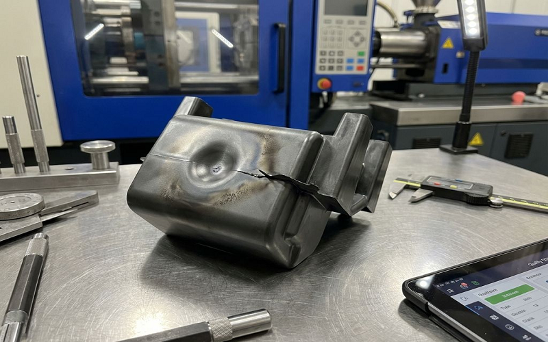
In the plastic injection molding process, sink marks are a common defect characterized by shallow depressions on the surface of molded parts. These sink marks not only affect the aesthetic quality of the product but may also indicate uneven internal material shrinkage.
The causes of sink marks are often not singular but result from a combination of part design, process parameters, mold cooling, and material properties.
This article will systematically outline the formation mechanism and main causes of sink marks, and will focus on comprehensive prevention and solutions from design to process, mold to material.
It aims to help manufacturers avoid pitfalls during product development and mass production, producing injection molded parts with better surface quality.
What Are Injection Molding Sink Marks?
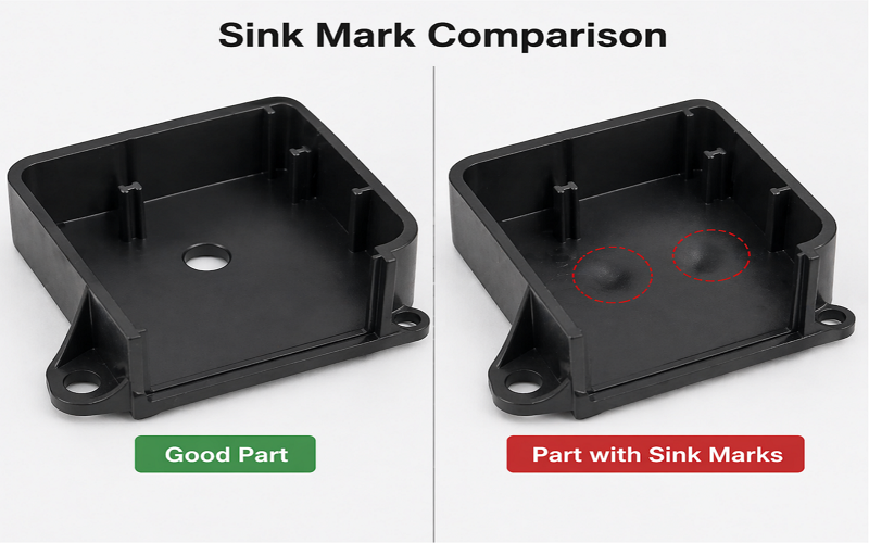
Sink marks are a common defect in the injection molding process, manifested as localized depressions or dimples on the surface of plastic parts.
They are usually shallow, but due to the uneven surface, they affect the gloss and appearance quality of the product, especially more noticeable on smooth or glossy surfaces.
Why Sink Marks Form?
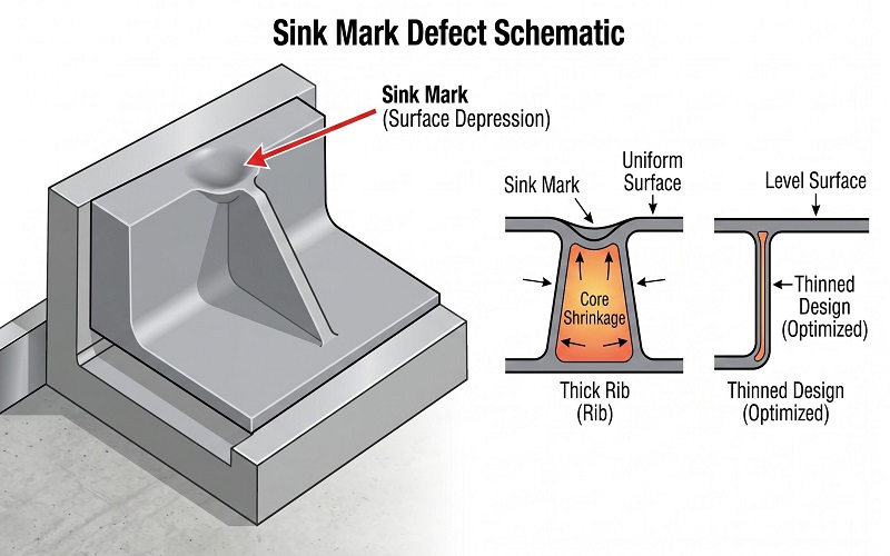
The formation mechanism of sink marks mainly originates from the non uniform cooling of the plastic during the volumetric shrinkage process.
During injection molding, the molten plastic first contacts the mold wall, and the outer portion of the part rapidly cools and solidifies to form a hard “shell,” while the thicker sections begin to cool more slowly as the molten plastic inside continues to shrink.
Due to the shrinkage of the internal material pulling, the already solidified outer surface area is pulled inward, forming a noticeable depression, i.e., a sink mark.
Common Locations Of Sink Marks
Sink marks typically found in thicker wall sections of plastic parts or near structural features like ribs, bosses, and other locations where the material is relatively thick and cooling is uneven.
These areas have larger wall thicknesses and slower cooling rates, causing internal shrinkage to be out of sync with the outer layer, making sink marks more likely to occur.
Impact Of Sink Marks For Injection Molded Part
Although sink marks generally do not significantly compromise the structural integrity or functionality of parts, they greatly diminish the product’s aesthetic quality.
Sink marks often disrupt the smooth reflection of light across the part, leading to uneven surface gloss that negatively impacts customer perception and the product’s market competitiveness.
Sink marks can also lead to dimensional inaccuracy affecting assembly, and parts exhibiting sink marks often fail quality control inspections, resulting in higher scrap rates.
Moreover, severe sink marks can indicate underlying internal stress concentrations or voids, which may indirectly affect the product’s durability and performance.
What Causes Sink Marks In Injection Molding?
Sink marks in injection molding are primarily caused by uneven volumetric shrinkage of the plastic resin during the cooling phase of the manufacturing process.
Several factors contribute to this phenomenon, ranging from plastic part design and material flow to mold temperature and process adjustments.
1. Part Design Adjustments (The Most Critical Fix)
- Non-uniform Wall Thickness: Sudden thickening of local walls causes slower cooling and greater shrinkage in thick-wall areas, leading to sink marks. Maintaining uniform nominal wall thickness is a key design principle to prevent sink marks.
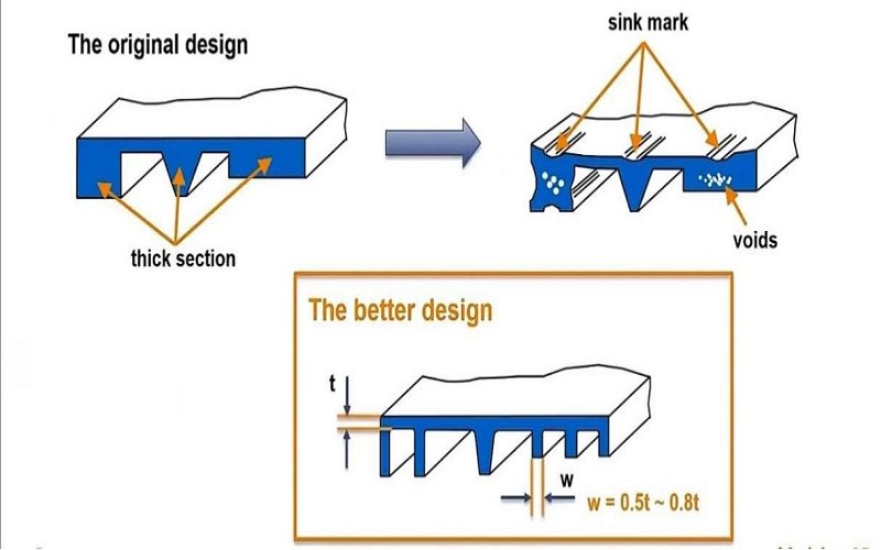
- Excessively Thick Ribs: The thickness of ribs should be controlled between 40% and 60% of the adjacent wall thickness. Overly thick ribs create localized thick sections that result in greater shrinkage and induce sink marks.
- Improper Boss Design: Bosses with excessive wall thickness or without proper coring cause local material accumulation and thick-wall areas, making sink marks more likely. Design should aim to thin boss walls and use reasonable coring.
2. Process Parameter Factors
- Low Packing Pressure: Inadequate packing pressure cannot effectively compensate for shrinkage in thick-wall areas, causing sink marks. Increasing packing pressure is an important method to control sink marks.
- Short Holding Time and Holding Pressure: Insufficient holding time and low holding pressure end the packing phase prematurely before the gate freezes, preventing further melt compensation and causing sink marks. Extending holding time and increasing holding pressure ensure gate freeze and adequate packing to minimize sink marks.
- Premature Gate Freeze: Small gate size or improper location causes early gate freeze, preventing packing pressure from reaching thick-wall areas and producing sink marks. Proper gate size and location design ensures effective packing.
- Excessive Melt Temperature or Improper Mold Temperature: High melt temperature increases plastic shrinkage rate, making sink marks more likely; excessively high or uneven mold temperature affects cooling speed and shrinkage uniformity. Adjusting temperature parameters optimizes cooling.
- Injection Speed and Complete Filling: Appropriately adjusting injection speed ensures filling completely, avoiding sink marks caused by incomplete filling.
3. Mold Design And Cooling Factors
- Insufficient Cooling Time: Improper layout of cooling channels leads to slower cooling in thick-wall areas, causing significant shrinkage differences and resulting in sink marks due to uneven cooling. Removing the part from the mold too early may cause the surface to collapse inward as the core continues to cool.
- Gate Design Issues: Small gate size or gate location far from thick-wall areas causes high pressure loss, making it difficult for packing pressure to be transmitted and causing sink marks. Optimizing gate size and position ensures sufficient material and pressure transmission.
- Non-uniform Mold Temperature Distribution: Temperature differences across the mold cause uneven plastic shrinkage and sink marks. Uniform mold temperature is maintained through proper cooling design and mold heating control.
- Venting Design: Poor mold venting traps air, affecting plastic flow and cooling, potentially causing sink marks. Ensuring good mold venting releases trapped air in the cavity.
4. Material Factors
- High Shrinkage Rates: Semi-crystalline materials (such as polypropylene PP, polyethylene PE, nylon PA) have higher shrinkage rates compared to amorphous materials (such as ABS, PC), making sink marks more likely. Selecting low-shrinkage materials or adding fillers reduces risks.
- Insufficient Drying of Materials: Moisture-sensitive materials (such as nylon, PC) with high moisture content cause processing defects and surface sink marks. Ensuring adequate drying prevents moisture impact.
- Material Selection: Choosing suitable materials considering melt temperature, shrinkage behavior, and processing characteristics reduces sink marks.
In summary, sink marks result from a combination of design, material, mold, and processing factors. Addressing these causes through careful design guidelines, proper material selection, and process adjustments is essential for eliminating sink marks and improving product quality.
How To Avoid And Control Sink Marks in Injection Molding?
Avoiding and controlling sink marks in injection molding requires a holistic approach that integrates part design, mold design, material selection, and process optimization. Each phase of the injection molding cycle must be carefully managed to minimize the conditions that lead to sink marks.
Design Phase: Emphasize Uniform Wall Thickness And Smart Feature Design
Careful attention during the design phase is crucial. Maintaining uniform wall thickness throughout the part helps ensure even cooling and reduces the risk of uneven shrinkage that causes sink marks. Coring out material in thick sections helps maintain surface integrity and prevents the formation of sink marks.
Using generous radii and smooth transitions between thick and thin sections helps promote consistent flow and minimizes stress concentrations.Designing cooling lines and channels thoughtfully ensures more uniform cooling throughout the part.
Skilled engineers should also position gates strategically to ensure molten plastic flows evenly into the mold cavity, especially towards thicker areas. This helps maintain enough material in critical sections during cooling, preventing sink marks.
Material Selection: Choose Low-Shrinkage Materials and Use Fillers
Selecting materials with inherently low shrinkage rates reduces the likelihood of sink marks. Amorphous plastics generally shrink less than semi-crystalline types. Use lighter colors and textured surfaces to minimize sink mark visibility.
Additionally, incorporating fillers such as glass fibers can improve dimensional stability and reduce volumetric shrinkage.
Mold Design: Optimize Cooling And Gate Placement
The mold cavity must be engineered to provide uniform cooling across the part. Uneven cooling is a primary cause of sink marks due to differential shrinkage rates.
Proper tooling design includes well-placed cooling channels that target thick areas and maintain consistent mold temperatures throughout the injection molding cycle.
Positioning gates near thick areas allows for effective packing pressure to be applied where it is most needed. Ensuring that gates are of adequate size prevents premature gate freeze, which can otherwise block packing pressure from compensating for shrinkage.
Process Changes: Control Packing, Cooling, and Temperature
Process parameters must be finely tuned to control sink mark formation. Increasing packing pressure and extending hold time ensures that enough material is packed into the mold cavity to compensate for volumetric shrinkage during cooling.
Sufficient cooling time allows the part to solidify fully before ejection, preventing the core from continuing to contract and pulling the surface inward.
Adjusting melt and mold temperatures to optimal levels reduces excessive shrinkage and promotes uniform cooling. Injection speed and cycle timing should be optimized to balance flow consistency and cooling efficiency.
In conclusion, preventing sink marks involves a comprehensive strategy encompassing the design phase, tooling design, process control, and material selection.
By maintaining uniform wall thickness, optimizing mold cavity and cooling design, carefully adjusting process parameters, and selecting suitable materials, manufacturers can effectively minimize sink marks.
Conclusion
Sink marks in injection molding are a common but preventable defect that primarily results from uneven cooling and volumetric shrinkage in thicker sections of plastic parts.
Although they rarely compromise structural integrity, sink marks can significantly affect surface quality, aesthetics, and dimensional accuracy, leading to increased scrap rates and reduced product competitiveness.
Addressing sink marks requires a comprehensive approach that includes careful part design with uniform wall thickness and optimized ribs and bosses, strategic mold design with proper cooling and gate placement, selection of low-shrinkage materials, and precise control of process parameters such as packing pressure, holding time, and temperature.
By integrating these design and manufacturing best practices, manufacturers can minimize sink marks, ensuring high-quality, visually appealing injection molded parts that meet both functional and cosmetic requirements.