
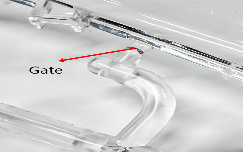
Gate design in injection molding is a critical factor that affects product quality and production efficiency. The gate not only determines how molten plastic enters the mold cavity but also directly influences the product’s appearance, mechanical properties, and production costs.
This raises a practical question faced by every mold designer and process engineer: how to choose the correct injection molding gate type for a specific product?
This article will delve into the basic concepts of injection molding gates, common types along with their advantages and disadvantages, and provide guidance on how to select the most suitable gate type based on product characteristics and production requirements.
What Is An Injection Molding Gate?
An injection molding gate is the small opening in a mold that connects the runner system to the mold cavity. Its primary function is to allow molten plastic to flow from the runner into the mold cavity during the injection process.
The gate controls the melt flow rate, pressure, and direction, which directly impacts how the cavity fills and ultimately affects the quality and characteristics of the molded part.
The gate acts as a critical transition point where the molten plastic changes from flowing through the runner to filling the complex geometry of the mold cavity.
It must be designed to freeze quickly after filling to trap the plastic inside the mold, ensuring proper packing and minimizing defects such as sink marks or voids.
Proper gate placement and design help achieve balanced filling, reduce the chance of air traps, and control weld line locations. The gate is therefore a vital feature in the injection molding process, balancing the technical requirements of flow, pressure, thermal effects, and cosmetic outcomes.
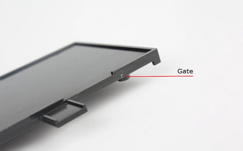
Why Gate Design And Location Matters In Injection Molding?
Gate design and location are fundamental to the success of the injection molding process because they directly influence several critical aspects of the final product and manufacturing efficiency.
Impact On Product Appearance
The position and type of the gate directly affect the appearance quality of the product. Improper gate placement can lead to obvious defects, flash, or weld marks, thereby reducing the appearance quality.
Gate size and geometry directly affect vestige height, fill time, packing effectiveness, and part cosmetics. Optimizing gate size is always a balance between competing requirements.
Small gate cross-sections increase shear rate and pressure drop, potentially causing burn marks and gate blush.
Larger gates improve packing and reduce pressure but leave bigger vestige and may increase trimming work. Controlling injection speed helps prevent air from being trapped and reduces shear-related defects.
Influence On Mechanical Properties
The gate controls how molten plastic flows into the cavity, which affects molecular orientation and stress distribution within the part. High shear through a small gate can affect the molecular orientation of the plastic, which in turn influences strength, residual stress, and potential warpage.
Improper design or placement may lead to weak weld lines, stress concentration, or anisotropic behavior that reduces the part’s overall performance. For example, gating into thick sections ensures adequate packing pressure to reduce sink marks and improve strength.
Effect On Production Efficiency And Cost
Gate design impacts cycle time, scrap rates, and post-processing labor. A gate that freezes too slowly can extend cooling time, increasing cycle duration.
Conversely, a gate that freezes too quickly may cause incomplete filling or short shots. Automatic degating gates like submarine or valve gates reduce manual trimming costs and speed up production.
Proper gate location helps avoid common injection molding defects such as air traps, voids, weld lines, and burn marks. For instance, placing gates in thick areas promotes uniform filling and reduces trapped air.
Controlling gate size and shape helps manage shear rates and pressure losses, preventing thermal degradation and flow hesitation.
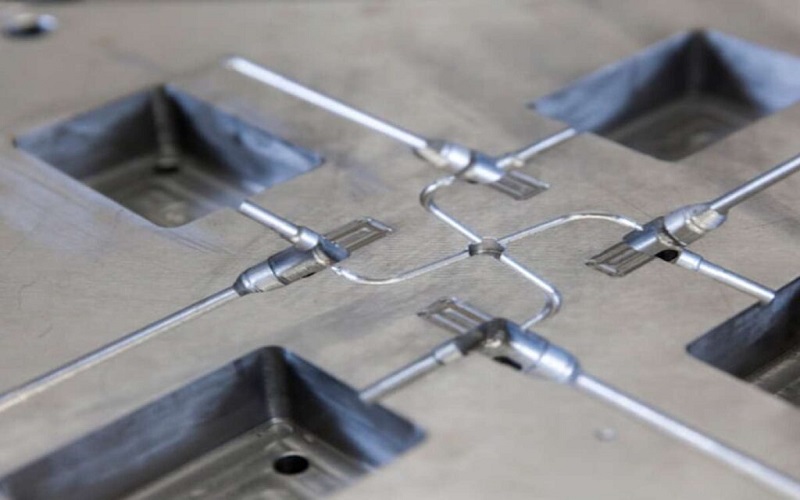
Common Types Of Injection Molding Gate
Different shapes of parts require different gate types for optimal filling. Below are the most commonly used options, each with distinct advantages, limitations, and applications.
Edge (side) Gate
This gate is machined at the parting line and feeds material into the side wall of the cavity. Edge gates are used for thin-walled components at the parting line.
They are easy to machine and adjust during trials, making them suitable for rectangular housings, covers, and industrial components. The downside is a visible tab-like gate mark that generally requires manual trimming.
Pin-point (pin) Gate
A small circular gate located in three-plate or hot runner molds. Pin point gates leave a minimal cosmetic mark on parts, often just a small dot.
Pin gates allow precise control of material flow in multi-cavity molds, making them popular for caps, closures, and consumer electronics components. The trade-off is higher pressure drop and potential shear issues with filled resins.
Tunnel (submarine) Gate
This gate enters below the parting line at approximately 30–45° and shears off automatically during ejection.
Submarine gates enable automatic degating during part ejection, which is ideal for high-volume parts like medical disposables or electrical connectors. Gate wear can become a maintenance concern with abrasive materials.
Fan Gate
Widens from the runner to the cavity like a fan, spreading the flow front across a wide area. Fan gates spread flow over a wide area to reduce injection pressure and improve fill uniformity for large, thin panels.
Using fan gates also reduces the chance of air traps. They are commonly used on automotive interior trim and appliance fronts. The wider vestige requires more trimming effort.
Film (flash) Gate
A thin, uniform gate running along a long edge of the part. It fills large, thin components like nameplates or diaphragms with even flow. Trimming is more labor-intensive due to the long flash line.
Direct Sprue Gate
Feeds directly from the sprue into the part center with minimal pressure loss. Direct gates provide a straight flow path with minimal pressure loss, making them suitable for large parts like gear blanks or thick disks. The vestige is large and requires significant trimming.
Tab Gate
Similar to the edge gate, but uses a wider gate tab to absorb shear forces, thereby protecting the product before the melt enters the cavity and preventing flow marks and burn marks.
This type of gate is especially suitable for shear-sensitive materials, such as PC/ABS blends. The gate tab is usually used for fine or thin-walled parts with high dimensional stability requirements.
Each gate type changes how easily you can control vestige, flow balance, and automatic degating.The next section explains the key factors you should evaluate when selecting the most suitable option for your specific application.
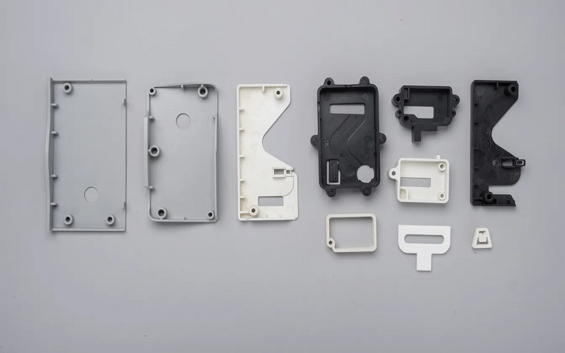
Key Factors For Choosing The Right Gate Type And Location
Choosing the appropriate injection molding gate type and location is a multifaceted decision that significantly impacts the final product’s quality, mechanical integrity, and manufacturing efficiency. Several key factors must be carefully considered to ensure optimal gating design:
Product Structure and Appearance Requirements
For products where appearance is critical, such as consumer electronics or automotive parts, gates must be placed in less visible or hidden areas to minimize cosmetic defects and gate vestige.
For example, an overlap gate or a submarine gate might be chosen because they leave minimal visible marks and can be automatically removed during ejection.
Complex product geometries, including round parts or components with multiple cavities, require careful gate placement to ensure uniform filling and to avoid weld lines or flow hesitation that could compromise structural integrity or aesthetics.
Material Characteristics
Materials with high viscosity or shear sensitivity require larger gate sizes or specific gate types to maintain proper flow without excessive pressure or shear-induced degradation. For example, crystalline materials may need larger gates to compensate for rapid freeze-off.
Material suppliers often provide guidelines on recommended gate types and sizes based on their resin’s flow properties. Additionally, filled materials, such as glass fiber-reinforced plastics, demand gates that minimize fiber breakage and maintain fiber orientation to ensure mechanical resistance.
Product Wall Thickness and Size
Thicker parts or those with significant wall thickness variation often need gates that allow adequate packing pressure and minimize sink marks.
For thin-walled or large surface area parts, gates that promote uniform flow distribution, like fan or film gates, are preferable to avoid flow hesitation and air traps.
Production Volume and Automation Needs
High-volume production benefits from gate types that enable automatic degating and reduce cycle times, such as submarine gates. For automated trimming and minimal manual intervention, gate choice and location must support these manufacturing goals.
Mold Design and Cost Constraints
The complexity and cost of mold fabrication influence gate selection. Simple gate designs like edge gates are easier and less expensive to machine and modify during trials. Complex gates like hot runner valve gates add cost but provide better control and reduced waste in high-cavity or cosmetic molds.
Filling Balance and Multi-Cavity Requirements
For molds with multiple cavities, gate location and type must ensure balanced flow to all cavities to avoid short shots or quality inconsistencies. Pin gates are often used for precise flow control in multi-cavity molds, while symmetrical gate placements promote balanced filling.
Identification and Sign Placement
In some cases, gate location is strategically chosen to serve as an identification mark or sign on the part, either for branding or quality control purposes. This functional use of the gate mark can influence gate type and placement.
By evaluating these factors in the context of the specific product, material, and manufacturing environment, designers can select the gate type and location that best balance quality, efficiency, and cost.
How To Control Gate Vestige?
Typical cosmetic specifications allow vestige height of less than 0.2 mm on non-visible surfaces. For high-end automotive Class A surfaces, requirements drop below 0.03 mm.
Factors Influencing Gate Vestige
Gate size and geometry directly affect vestige height, fill time, packing effectiveness, and part cosmetics.
- Gate Size and Shape: Larger gates generally leave bigger vestiges, requiring more trimming. The gate shape (circular, rectangular, fan-shaped) also influences the vestige profile and ease of removal.
- Gate Location: Placing the gate on less visible or recessed areas reduces the visual impact of the vestige. For example, submarine gates leave small scars on side walls, often hidden from view.
- Material Flow and Cooling: Rapid cooling at the gate can cause premature solidification, leading to a rough or uneven vestige surface. Controlled cooling and optimized gate design help minimize this.
- Injection Parameters: Injection speed, pressure, and temperature affect how the melt flows through the gate and solidifies. Optimizing these molding parameters can reduce gate blush and improve vestige quality.
- Mold Surface Finish: A polished gate land reduces friction and shear, leading to smoother gate vestiges and easier part ejection.
Techniques To Minimize Gate Vestige
- Use of Valve Gates: Valve gates in hot runner systems provide precise control over gate opening and closing, resulting in minimal vestige and improved cosmetic quality.
- Automatic Degating Gates: Submarine or tunnel gates shear off automatically during ejection, eliminating the need for manual trimming and reducing cycle time.
- Gate Land Polishing: Regular polishing of the gate land area in the mold reduces surface roughness and prevents gate blush.
- Optimized Gate Design: Designing gates with tapered or rounded edges helps reduce stress concentration and improves vestige appearance.
- Gate Size Optimization: Balancing gate size to ensure adequate flow while minimizing vestige size is critical. Simulation tools can assist in finding the optimal gate dimensions.
Controlling gate vestige is essential for achieving high cosmetic standards and efficient production. It requires a combination of thoughtful gate design, precise process control, and appropriate material selection.
By addressing these factors, manufacturers can produce parts with minimal gate marks, reducing the need for costly post-processing and enhancing overall product quality.

How To Choose The Right Type Of Injection Molding Gate?
Choosing the right type of injection molding gate is a key step to ensure product quality and production efficiency. The following detailed selection process helps you systematically evaluate various factors and make a scientific and reasonable decision:
Step 1 – Define cosmetic and functional faces. Mark A-surfaces and critical features on CAD. Identify zones where no gate vestige is allowed and where weld lines are acceptable. Note features like vents, snap fits, and sealing surfaces that restrict gate position.
Step 2 – Analyze material data. Review melt flow index, viscosity, shear sensitivity, and recommended gate types from material datasheets or supplier design guides. Semi-crystalline materials like PA and POM often need larger gates to compensate for rapid freeze-off.
Step 3 – Map flow lengths and wall transitions. Identify the maximum thickness zones and longest flow paths. Prefer gate locations that shorten flow distance and pack heavy regions effectively. Flow direction should feed from thick to thin sections.
Step 4 – Pre-select 1–2 candidate gate types and sizes. For example, compare an edge gate located near a rib cluster against a tunnel gate that allows automatic degating on the same part. Estimate gate depth at approximately 50–80% of wall thickness for rectangular gates.
Step 5 – Validate with simulation. Use moldflow or similar CAE tools for analysis of filling pattern, pressure, weld line positions, and clamp tonnage. Adjust gate location and type as required. Vacuum assistance significantly lowers air entrapment in molds when combined with proper venting.
Step 6 – Confirm during T0/T1 trials. Measure actual gate freeze time by stepping up hold time until part mass stops increasing. Observe gate blush, splay, or flash. Fine-tune gate size, polish the gate land, or adjust temperature to reach final specification.

Conclusion
The injection molding gate is a small feature with outsized influence on melt flow, weld lines, cosmetic marks, and production economics.
There is no universal best gate type: edge, pin, tunnel, fan, film, direct, and valve gates each serve different geometry, material, and volume needs.
Successful projects typically combine early cross-functional reviews between design, tooling, and processing teams with simulation-driven gate decisions before releasing mold designs.
FAQ
How do I know if my existing gate size is too small or too large?
A gate that is too small shows symptoms like abnormally high injection pressure, burn marks or discoloration near the gate area, short shots, and gate blush.
A gate that is too large creates excessive vestige that requires heavy trimming, longer cooling times in the gate zone, and potentially overpacked regions near the gate that cause stress or warpage.
Monitoring part weight at varying hold times is a quick way to assess whether the gate is freezing too early or too late.
Can I move or change a gate after the mold is already built?
Yes, but it is expensive. The typical approach involves welding the existing gate closed, remachining a new gate in the desired location, and re-polishing.
In some cases, a gated insert can be replaced. Adding multiple gates to an existing tool is possible but may require new runner channels machined into the mold plates. Budget at least several thousand dollars and one to three weeks of downtime for such modifications.
Which gate types work best for clear parts like lenses and light pipes?
Clear parts demand minimal shear and no jetting, because turbulence near the gate causes birefringence and hazing. Fan gates or edge gates placed in non-optical zones are commonly used.
Valve gates are preferred when the gate must be located on a visible surface, as they produce a nearly flush gate scar. In all cases, the flow front should travel smoothly without abrupt direction changes.
What special considerations apply to glass-filled materials at the gate?
Glass fibers increase melt viscosity and cause abrasion at the gate land. Gates should be larger than for unfilled resins to reduce fiber breakage and shear damage. Hardened steel inserts or wear-resistant coatings in the gate area extend tool life.
Avoid gate geometries that squeeze fibers through extremely narrow openings, as this degrades mechanical properties and can cause visible fiber whitening on the part surface.
Is there a simple way to estimate gate freeze time during trials?
A practical shop-floor technique is to mold parts at increasing hold (packing) times while weighing each shot. When additional hold time no longer increases part mass, the gate has frozen and no more material can enter the cavity.
This point marks your effective gate freeze time and helps you set optimal packing parameters without specialized instrumentation.